Description
API 16C Choke and Kill Hose for BOP, Drilling Spool & Choke Manifold Applications
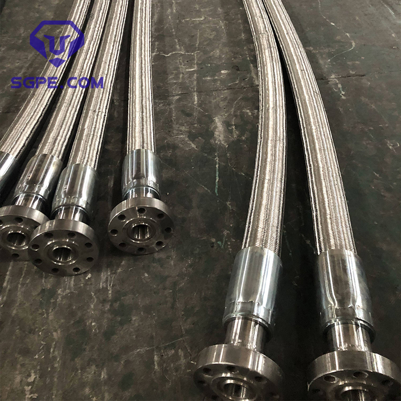
SGPE supplies API 16C Choke and Kill Hose assemblies for high-pressure drilling and well control systems. These flexible pressure-containing lines connect critical equipment such as the BOP stack, drilling spool, choke manifold and kill manifold while allowing controlled movement between rigid components.
Typical project requirements include 5,000 PSI, 10,000 PSI and 15,000 PSI, together with selected 20,000 PSI Choke and Kill Hose configurations. Common hose I.D.s range from 2″ to 4″, depending on the pressure class and qualified hose design.
Projects can specify FSL 0, FSL 1, FSL 2 or FSL 3, custom overall lengths, different End A and End B connections, H2S / sour-service requirements, high-temperature service, project-specific fire protection and stainless steel external armor.
Depending on the installation position, the same product may also be described as an API 16C Flexible Choke and Kill Line, Flexible Choke Hose, Flexible Kill Hose, BOP Choke Hose, BOP Kill Hose, High Pressure Choke Hose, High Pressure Kill Hose, Choke Manifold Hose, Kill Manifold Hose, Drilling Spool Choke Hose, Drilling Spool Kill Hose or Well Control Hose.
SGPE treats the hose as part of the complete well control system rather than as an isolated component. Technical review can cover the BOP pressure class, drilling spool outlets, choke and kill manifold interfaces, hose routing and both end connections before the final assembly is confirmed.
This approach supports land and offshore drilling contractors, oil and gas operators, rig manufacturers, EPC companies, well control contractors, BOP service companies, oilfield distributors and MRO buyers.
For an accurate API 16C Choke and Kill Hose quotation, provide the working pressure, hose I.D., FSL, overall length, End A, End B, operating temperature, working medium, H2S requirement and installation layout.
Email: info@sgpe.com
Tel / WhatsApp: +86 186-1599-5239
Product at a Glance
| Item | Typical Project Requirement |
|---|---|
| Product | API 16C Choke and Kill Hose |
| Product Type | Flexible Choke and Kill Line |
| Standard | API Spec 16C |
| Main Service | BOP choke line / BOP kill line |
| Working Pressure | 5,000 / 10,000 / 15,000 PSI; selected 20,000 PSI |
| FSL | FSL 0 / FSL 1 / FSL 2 / FSL 3 |
| Common Hose I.D. | 2″, 2-1/2″, 3″, 3-1/2″, 4″, depending on configuration |
| Overall Length | Custom according to equipment layout |
| Minimum Bend Radius | According to qualified hose design |
| End Connections | Flange, hub or approved project-specific termination |
| Working Media | Drilling mud, kill fluid and specified wellbore fluids |
| Sour Service | H2S / CO2 configuration according to project requirements |
| External Protection | Project-specific fire protection or stainless steel armor |
| Typical Equipment | BOP, drilling spool, choke manifold, kill manifold |
Selection Note: The approved SGPE datasheet, drawing and purchase specification govern the final hose assembly. Working pressure alone does not determine the correct API 16C hose.
What Is a Flexible Choke and Kill Line?
An API 16C Choke and Kill Hose is a flexible high-pressure line installed within the BOP and choke-and-kill pressure-control circuit.
It performs a different function from an API 7K drilling hose. API 7K Rotary and Vibrator Hoses mainly carry drilling mud during normal circulation, while an API 16C Flexible Choke and Kill Line forms part of the well control system.
During a kick or another well control event, the drilling crew needs controlled flow paths to manage wellbore pressure.
The choke line carries wellbore fluid from the BOP stack or drilling spool toward the choke manifold, where the choke equipment controls flow and backpressure.
The kill line provides a high-pressure path for pumping weighted drilling mud or another specified kill fluid toward the BOP and well.
Rigid piping works well where equipment remains fixed and aligned. Drilling rigs, however, experience vibration, repeated rig-up, dimensional variation and structural movement. A flexible choke or kill line accommodates this controlled movement while maintaining the required pressure-containing flow path.
Correct selection therefore considers the working pressure, hose I.D., FSL, minimum bend radius, overall length, End A and End B, operating temperature, service medium, H2S conditions and actual installation geometry.
Choke Hose vs. Kill Hose
| Item | Choke Hose | Kill Hose |
|---|---|---|
| Typical Flow Path | BOP / drilling spool → choke manifold | Kill manifold / pump → BOP / drilling spool |
| Main Function | Routes well flow toward the choke system | Pumps kill fluid toward the well |
| Typical Media | Drilling mud, formation fluid, gas-cut mud, wellbore fluid | Weighted drilling mud / kill fluid |
| Main Equipment | BOP, drilling spool, choke manifold | Kill manifold, pumping circuit, BOP |
| Common Product Term | BOP Choke Hose / Flexible Choke Line | BOP Kill Hose / Flexible Kill Line |
| Main Selection Focus | Pressure, FSL, abrasion, H2S, length, ends | Pressure, bore, FSL, length, ends |
A BOP Choke Hose carries wellbore fluid toward the choke manifold, while a BOP Kill Hose carries kill fluid toward the well.
The hose construction can be similar, but the installation position, flow function and connected equipment differ. Every RFQ should therefore identify the required assembly clearly as either a Choke Line or Kill Line.
Technical Specifications
| Technical Parameter | Typical Range / Configuration |
|---|---|
| Standard | API Spec 16C |
| Product Type | Flexible Choke and Kill Line |
| FSL | FSL 0 / FSL 1 / FSL 2 / FSL 3 |
| Rated Working Pressure | 5,000 / 10,000 / 15,000 PSI; selected 20,000 PSI |
| Metric Pressure Reference | Approx. 34.5 / 69 / 103.5 / 138 MPa |
| Typical Hose I.D. | 2″ / 2-1/2″ / 3″ / 3-1/2″ / 4″, depending on configuration |
| Test Pressure | According to approved pressure class and hose design |
| Minimum Burst Pressure | According to qualified hose design |
| Minimum Bend Radius | Design-specific |
| Overall Length | Custom |
| Inner Liner | Selected for fluid, temperature and abrasion |
| Reinforcement | High-pressure multi-layer reinforcement |
| Outer Protection | Oilfield-service protective construction |
| External Armor | Available where specified |
| End Termination | Flange, hub or approved project-specific connection |
| End A / End B | Same or different configurations |
| Operating Temperature | According to approved project datasheet |
| Sour Service | H2S / CO2 requirement reviewed separately |
| Offshore / Subsea Service | Subject to project-specific engineering review |
| Inspection | According to PO / ITP |
| Third-Party Inspection | Available when specified |
| Documentation | Datasheet, drawing, test and inspection records |
Working Pressure, Test Pressure & Burst Pressure
Pressure class is one of the first selection points for a High Pressure Choke and Kill Hose, but pressure alone does not define the assembly. The hose must also suit the connected BOP and manifold equipment, bore size, FSL and actual service conditions.
| Rated Working Pressure | Metric Reference | Test Pressure | Minimum Burst Pressure |
|---|---|---|---|
| 5,000 PSI | Approx. 34.5 MPa | 7,500 PSI | 11,250 PSI |
| 10,000 PSI | Approx. 69 MPa | 15,000 PSI | 22,500 PSI |
| 15,000 PSI | Approx. 103.5 MPa | 22,500 PSI | 33,750 PSI |
| 20,000 PSI | Approx. 138 MPa | 30,000 PSI | 45,000 PSI |
These figures provide project references. The final approved datasheet controls the technical requirement.
A 3 Inch 10000 PSI Choke Hose, for example, still requires the correct FSL, temperature range, overall length, end connections and minimum bend radius.
Likewise, a 15K FSL 3 Choke and Kill Hose must match the pressure class and interfaces of the BOP, drilling spool and manifold system.
Reference Hose Size & Minimum Bend Radius Matrix
Minimum Bend Radius, or MBR, does not have one universal value for every API 16C hose. The qualified hose construction determines the final limit.
| Hose I.D. | Working Pressure | Test Pressure | Min. Burst Pressure | Reference MBR |
|---|---|---|---|---|
| 2″ / 50.8 mm | 5,000 PSI | 7,500 PSI | 11,250 PSI | 900 mm |
| 2-1/2″ / 64 mm | 5,000 PSI | 7,500 PSI | 11,250 PSI | 1,000 mm |
| 3″ / 76.2 mm | 5,000 PSI | 7,500 PSI | 11,250 PSI | 1,000 mm |
| 3-1/2″ / 89 mm | 5,000 PSI | 7,500 PSI | 11,250 PSI | 1,100 mm |
| 4″ / 101.6 mm | 5,000 PSI | 7,500 PSI | 11,250 PSI | 1,200 mm |
| 2″ / 50.8 mm | 10,000 PSI | 15,000 PSI | 22,500 PSI | 1,000 mm |
| 2-1/2″ / 63.5 mm | 10,000 PSI | 15,000 PSI | 22,500 PSI | 1,100 mm |
| 3″ / 76.2 mm | 10,000 PSI | 15,000 PSI | 22,500 PSI | 1,150 mm |
| 3-1/2″ / 89 mm | 10,000 PSI | 15,000 PSI | 22,500 PSI | 1,200 mm |
| 4″ / 101.6 mm | 10,000 PSI | 15,000 PSI | 22,500 PSI | 1,250 mm |
| 2″ / 50.8 mm | 15,000 PSI | 22,500 PSI | 33,750 PSI | 1,000 mm |
| 2-1/2″ / 63.5 mm | 15,000 PSI | 22,500 PSI | 33,750 PSI | 1,150 mm |
| 3″ / 76.2 mm | 15,000 PSI | 22,500 PSI | 33,750 PSI | 1,200 mm |
| 2″ / 50.8 mm | 20,000 PSI | 30,000 PSI | 45,000 PSI | 900 mm |
| 2-1/2″ / 64 mm | 20,000 PSI | 30,000 PSI | 45,000 PSI | 1,100 mm |
| 3″ / 76.2 mm | 20,000 PSI | 30,000 PSI | 45,000 PSI | 1,200 mm |
Engineering Note: Confirm the final MBR, hose O.D., assembly weight and end-fitting dimensions against the approved SGPE project datasheet before installation.
5K, 10K, 15K & Selected 20K Configurations
5,000 PSI Choke and Kill Hose
A 5000 PSI Choke and Kill Hose suits many conventional land-rig and surface well control systems.
Common project requirements include 2″, 3″, 3-1/2″ and 4″ hose I.D.s, depending on the required flow area and manifold design. A 5K assembly can also require a custom overall length, H2S service or different connections at each end.
10,000 PSI Choke and Kill Hose
A 10000 PSI Choke Hose serves high-pressure BOP, drilling spool and manifold systems.
Typical requirements include a 2″ 10K Choke Hose, 2-1/2″ 10K Kill Hose, 3″ 10000 PSI Choke and Kill Hose or 4″ 10K Flexible Kill Line.
At this pressure level, FSL, MBR, connection geometry, operating temperature and hose routing need careful review.
15,000 PSI Choke and Kill Hose
A 15000 PSI Choke and Kill Hose supports deep-well and high-pressure drilling programs.
Common configurations include 2″, 2-1/2″ and 3″ hose I.D.s, depending on the qualified design. Projects can also specify FSL 3, H2S service, custom end terminations and enhanced inspection requirements.
Selected 20,000 PSI Choke and Kill Hose
Selected ultra-high-pressure projects can require a 20K Flexible Choke and Kill Line.
Because bore size, FSL, operating temperature, end connections and routing all affect the final configuration, provide the complete project specification before requesting a 20K quotation.
FSL 0, FSL 1, FSL 2 & FSL 3
FSL means Flexible Specification Level.
API 16C Flexible Choke and Kill Line projects can specify FSL 0, FSL 1, FSL 2 or FSL 3. The operator, drilling contractor or EPC normally defines the required level in the project specification.
FSL should follow the actual requirement rather than an assumption that a higher number automatically represents the correct choice.
When a project requires an FSL 3 Choke and Kill Hose, identify FSL 3 during the RFQ stage so the pressure class, hose design, inspection requirements and documentation scope can be reviewed together.
Pressure, FSL and operating conditions should always be treated as one selection package.
Hose Construction & Protection Options
Fluid-Contact Inner Liner
The inner liner contacts drilling and wellbore fluids directly, so the service medium plays an important role in hose selection.
Water-based mud, oil-based mud, weighted kill fluid, formation fluids, gas-cut mud, barite, drilled solids, H2S, CO2 and operating temperature can all affect liner requirements.
Choke service can also expose the hose to high fluid velocity and abrasive solids. For severe service, provide available mud density, solids information and fluid composition during technical review.
High-Pressure Reinforcement
The reinforcement carries the internal pressure load while maintaining controlled flexibility.
Two hoses with the same nominal I.D. can use different constructions when pressure rating, FSL, temperature or operating conditions change.
Outer Protection
The outer construction protects the pressure-containing hose during handling and oilfield operation.
Projects that expose the line to structural contact, repeated rig handling or harsh offshore conditions can require additional external protection.
Project-Specific Fire Protection & Armor
Some projects specify additional fire protection or stainless steel external armor.
Fire protection should follow the operator or project specification. Stainless steel armor also needs separate review because it changes hose O.D., weight, flexibility and support requirements.
Both should be considered together with the MBR and final installation route.
End Terminations
End terminations transfer pressure and mechanical loads between the flexible hose and rigid equipment.
End A and End B therefore form part of the complete pressure-containing assembly and require proper interface review.
If a project specification defines bonded or non-bonded construction, bore construction or another specific hose design, include that information in the RFQ rather than assuming it from the product name.
Typical Well Control Applications
| Oilfield Application | Typical Product Term | Main Selection Focus |
|---|---|---|
| BOP Choke Outlet | BOP Choke Hose | Pressure, fluid and manifold interface |
| BOP Kill Outlet | BOP Kill Hose | Pressure and kill circuit |
| Drilling Spool Choke Outlet | Drilling Spool Choke Hose | Connection geometry |
| Drilling Spool Kill Outlet | Drilling Spool Kill Hose | Pressure and flow |
| BOP to Choke Manifold | BOP-to-Choke Manifold Hose | FSL, length and routing |
| Kill Manifold to BOP | Kill Manifold Hose | Pressure and connection |
| Land Drilling Rig | Oilfield Choke Hose | Vibration and rig-up tolerance |
| Jack-Up Rig | Offshore Choke Hose | Movement and environment |
| Fixed Offshore Platform | Offshore Flexible Choke Line | Environment and documentation |
| High-Pressure Well | 10K / 15K Choke Hose | Pressure and FSL |
| Sour Well | H2S Choke Hose | H2S, CO2 and materials |
| Abrasive Mud Service | Abrasion-Resistant Choke Hose | Liner and solids |
| BOP Upgrade | Custom API 16C Hose | New equipment interfaces |
| Rig Refurbishment | Replacement API 16C Hose | Existing geometry |
| Scheduled MRO | Replacement Choke Hose | Identification and fit |
| EPC Well Control Package | Project-Specific Flexible Line | Datasheet, ITP and MDR |
Land, Offshore & Harsh-Service Applications
Land Drilling Rigs
Land rigs often use Flexible Choke and Kill Lines where rigid piping cannot easily accommodate BOP vibration, repeated rig-up, manifold positioning or equipment alignment.
The hose may connect a drilling spool to the choke manifold, connect the kill circuit to the BOP stack or provide a flexible interface after a BOP or manifold upgrade.
For these installations, review the equipment arrangement before finalizing the hose length and end connections.
Offshore Drilling
Offshore projects introduce additional movement, environmental exposure and documentation requirements.
A jack-up rig or fixed offshore platform may use an Offshore Choke and Kill Hose between surface BOP equipment and the choke or kill manifold. Replacement projects may also require the new hose to follow the existing route, support arrangement and connection orientation.
For dynamic or subsea applications, provide the complete engineering specification. External pressure, movement, water depth and interface requirements need separate technical review before the supply scope is confirmed.
H2S & Sour Service
Choke lines can carry fluids directly from the wellbore. Sour wells can therefore expose the hose and metallic end components to H2S, CO2, water and other corrosive constituents.
For an H2S Choke Hose or Sour Service Choke and Kill Hose, provide available H2S and CO2 information, operating pressure, temperature and well-fluid data.
If NACE MR0175 / ISO 15156 requirements apply to relevant metallic components, include them in the project specification.
Pressure rating alone does not confirm sour-service suitability.
Abrasive Mud Service
Weighted drilling mud can contain barite, drilled solids and other abrasive materials.
When severe abrasion applies, provide mud density, solids information, operating pressure and temperature so the hose bore and liner can be reviewed against actual service conditions.
Minimum Bend Radius, Overall Length & Hose Routing
Minimum Bend Radius defines how tightly the hose can bend within its qualified design.
A high-pressure Choke and Kill Hose contains substantial reinforcement, so it cannot bend like a small hydraulic hose.
Incorrect routing can create tight bends near the end fittings, excessive tension, twisting, unsupported weight or contact with surrounding steelwork. A hose can therefore have the correct pressure rating and bore yet still be unsuitable for the available installation space.
Overall length matters for the same reason. A hose that is too short can load the end terminations, while excessive length can create unwanted sag or an unsuitable bend.
Whenever an installation drawing is available, MBR, overall length, End A, End B, hose routing and expected equipment movement should be reviewed together.
End Connections & Equipment Interfaces
The end connections must match the actual BOP, drilling spool and manifold interfaces.
SGPE can review flange, hub and other approved project-specific high-pressure terminations.
| Connection Data | Information Required |
|---|---|
| End A Size | Complete designation |
| End A Pressure | Pressure class |
| End A Type | Flange / hub / project type |
| End B Size | Complete designation |
| End B Pressure | Pressure class |
| End B Type | Flange / hub / project type |
| Sealing Interface | Groove / sealing information |
| Connected Equipment | BOP / drilling spool / choke manifold / kill manifold |
| Orientation | Where required |
| Drawing | Strongly recommended |
End A and End B do not need to use the same connection.
For a BOP-to-Choke Manifold Hose, one termination must match the BOP or drilling spool outlet while the other matches the choke manifold interface.
For replacement work, clear photographs of both terminations help with preliminary identification. An original drawing or verified dimensional specification provides the strongest basis for final matching.
Replacement Choke and Kill Hose
Replacement is one of the most common high-intent API 16C procurement scenarios.
A drilling contractor may need a new hose after scheduled maintenance, failed inspection, external damage, BOP overhaul, manifold replacement, rig refurbishment or a change in the pressure-control system.
A correct Replacement API 16C Choke and Kill Hose must match more than pressure and bore.
| Replacement Data | Why It Matters |
|---|---|
| Existing Nameplate | Identifies basic hose information |
| Original Datasheet | Confirms technical specification |
| Original Drawing | Confirms geometry |
| Working Pressure | Confirms pressure class |
| Hose I.D. | Confirms bore |
| FSL | Confirms project requirement |
| Overall Length | Maintains installation fit |
| End A | Matches BOP / drilling spool |
| End B | Matches manifold |
| Minimum Bend Radius | Confirms routing |
| Operating Temperature | Confirms service |
| Working Medium | Supports liner review |
| H2S / CO2 | Supports sour-service review |
| External Armor | Confirms protection |
| Full Hose Photo | Shows complete assembly |
| End Photos | Supports connection identification |
| Installation Photos | Shows actual routing |
| Existing Part Number | Supports cross-reference |
If the original documents are unavailable, technical review can begin with the nameplate, full hose photograph, both end connections and verified field dimensions.
This reduces the risk of receiving a Replacement BOP Choke Hose with the correct pressure rating but the wrong length, end termination or installation geometry.
Custom API 16C Flexible Lines
Not every BOP or manifold system uses a standard hose arrangement.
SGPE reviews custom requirements for special overall lengths, different End A and End B connections, project-specific BOP interfaces, external armor, H2S service or other non-standard operating conditions.
Custom configurations can cover 5K, 10K and 15K pressure classes, selected 20K projects and FSL 0–3.
This support is particularly useful for new BOP packages, rig upgrades, brownfield modifications and replacement projects where standard hose dimensions or end terminations do not match the existing equipment.
For buyers sourcing an API 16C Choke and Kill Hose Supplier in China, SGPE can review both the flexible line and the connected well control interfaces before preparing the technical proposal.
Inspection, Testing & Documentation
Oilfield operators, drilling contractors and EPC companies often require a defined quality and documentation package with the hose.
Depending on the purchase order and project specification, SGPE can coordinate the approved datasheet and drawing, dimensional inspection, end-connection verification, pressure testing and test records. The agreed documentation package can also include a Certificate of Conformity, applicable material documents, customer or third-party inspection records, ITP witness points and final MDR documentation.
For EPC and operator-controlled projects, provide the ITP, MDR and other documentation requirements during the RFQ stage whenever possible. Defining the inspection and documentation scope before production helps avoid late changes after the assembly has already been completed.
Support for EPC, Drilling Contractors & Oilfield MRO
EPC Projects
EPC contractors often provide a structured technical package containing the datasheet, FSL, connection drawings, BOP and manifold interfaces, ITP and MDR requirements.
Reviewing these documents together is particularly useful when different vendors supply the BOP, drilling spool and manifold.
Drilling Contractors
A drilling contractor may have only the BOP drawing, manifold drawing, working pressure, hose I.D., required length and field layout.
These references can be used to identify missing parameters and build a clearer hose specification before quotation.
Oilfield MRO & Replacement
MRO buyers sometimes begin with only an existing hose, nameplate, part number, field photographs and several measured dimensions.
This information can provide a practical starting point for BOP overhaul, rig refurbishment, brownfield modification, obsolete hose replacement and scheduled well control maintenance.
Related BOP & Well Control Equipment from SGPE
An API 16C Flexible Choke and Kill Line forms one part of the complete pressure-control system.
SGPE also supports related well control equipment, allowing several pressure and connection interfaces to be reviewed through one supplier.
| Related Equipment | Relationship to Choke / Kill Hose |
|---|---|
| API 16A Ram BOP | Choke / kill system interface |
| API 16A Annular BOP | BOP stack component |
| API 16A Drilling Spool | Choke and kill outlet connection |
| API 16C Choke Manifold | Choke-line destination |
| Kill Manifold | Kill-line pressure circuit |
| Drilling Choke | Well pressure regulation |
| API 6A Gate Valve | High-pressure isolation |
| API 6A Flanges | Pressure connection |
| Adapter Spools | Interface transition |
| Double Studded Adapters | Pressure crossover connection |
| BOP Control System | Well control package |
| API 7K Rotary Hose | Drilling mud circulation |
| API 7K Vibrator Hose | Mud pump discharge |
For new well control packages, coordinated sourcing can simplify pressure-class matching, connection review and project documentation.
For MRO projects, buyers can purchase only the required replacement hose while retaining the existing BOP and manifold equipment.
Why Choose SGPE for API 16C Hose Requirements?
SGPE focuses on petroleum drilling, wellhead and well control equipment, so hose selection does not stop at the working-pressure number.
When project information is available, the Flexible Choke and Kill Line can be reviewed together with the BOP, drilling spool, choke manifold and kill manifold interfaces. This system-level approach helps reduce connection, routing and dimensional errors before production.
SGPE supports common 5K, 10K and 15K Choke and Kill Hose requirements together with selected 20K projects. Project review can also cover FSL 0–3, H2S service, offshore installations, abrasive drilling fluids, custom overall lengths and different End A / End B configurations.
Replacement projects often begin with incomplete engineering information. Existing nameplates, drawings, photographs and verified dimensions can provide a practical basis for technical review.
For EPC and operator-controlled projects, SGPE can coordinate project-specific datasheets, drawings, inspection requirements, third-party inspection and final documentation according to the agreed supply scope.
Because SGPE also supports BOPs, drilling spools, choke manifolds, kill manifolds, API 6A valves, flanges, adapters and BOP control equipment, buyers can review several well control interfaces through one supplier.
API 16C Hose Price, Quote & Lead Time
The final API 16C Choke and Kill Hose price depends on the actual configuration rather than working pressure alone.
A standard 3″ 10K Choke Hose differs significantly from a 15K FSL 3 Choke and Kill Hose requiring H2S service, custom end connections, external armor and third-party inspection.
| Procurement Factor | Effect on Quote / Delivery |
|---|---|
| Working Pressure | Changes hose construction |
| Hose I.D. | Changes material and assembly size |
| Overall Length | Changes material requirement |
| FSL | Changes technical and qualification scope |
| End A / End B | Changes termination configuration |
| Operating Temperature | Changes hose requirement |
| Working Medium | Affects liner selection |
| H2S / Sour Service | Adds service requirements |
| External Armor | Adds protection scope |
| Fire Requirement | Changes project scope |
| Offshore / Subsea Service | Adds engineering review |
| Replacement Matching | Adds interface verification |
| Third-Party Inspection | Adds inspection coordination |
| MDR / Documentation | Adds documentation scope |
| Quantity | Affects production planning |
| Technical Approval | Affects production release and lead time |
For an accurate API 16C Hose quote and lead time, provide the actual technical specification rather than requesting only a generic 10K or 15K hose price.
Once the configuration is confirmed, SGPE can prepare the corresponding API 16C Hose datasheet, technical proposal, commercial quotation and delivery information.
RFQ Data Sheet
| RFQ Parameter | Information to Provide |
|---|---|
| Service | Choke Line / Kill Line |
| Quantity | Required assemblies |
| Rig Type | Land / offshore / project-specific |
| Working Pressure | 5K / 10K / 15K / selected 20K |
| Hose I.D. | Required bore |
| FSL | FSL 0 / 1 / 2 / 3 |
| Operating Temperature | Minimum / maximum |
| Overall Length | Required length |
| End A | Complete designation |
| End B | Complete designation |
| Connection Drawing | Preferred |
| Minimum Bend Radius | If defined |
| Working Medium | Mud / kill fluid / wellbore fluid |
| Mud Density / Solids | If relevant |
| H2S / CO2 | Available service data |
| Sour-Service Requirement | If applicable |
| Fire Protection | If required |
| External Armor | If required |
| Inspection / TPI | Required scope |
| ITP / MDR | If applicable |
| Existing Datasheet / Drawing | Replacement project |
| Nameplate | Clear photograph |
| Hose / End Photos | Replacement project |
| Installation Photos | Existing routing |
| Existing Part Number | If available |
| Required Delivery | Project schedule |
| Destination | Country / project location |
If complete technical information is unavailable, start with the nameplate, one full hose photograph and clear photographs of both end connections.
SGPE can use these references to identify the remaining technical questions before preparing a quotation.
Frequently Asked Questions About API 16C Choke and Kill Hose
1. What is an API 16C Choke and Kill Hose?
An API 16C Choke and Kill Hose is a flexible high-pressure line used in BOP and well control systems to connect equipment such as the BOP stack, drilling spool, choke manifold and kill manifold.
A choke hose normally carries wellbore fluid from the BOP or drilling spool toward the choke manifold, while a kill hose provides a high-pressure path for pumping kill fluid toward the well.
Depending on its installation position, the same product may also be described as an API 16C Flexible Choke and Kill Line, BOP Choke Hose, BOP Kill Hose, Choke Manifold Hose, Drilling Spool Choke Hose or Well Control Hose. These flexible lines are commonly used on land rigs, offshore platforms and other high-pressure drilling installations where rigid piping cannot easily accommodate movement or equipment alignment.
2. What is the difference between a Choke Hose and a Kill Hose?
A Choke Hose and a Kill Hose form part of the same well control system, but they perform different functions.
The choke hose normally routes wellbore fluid from the BOP stack or drilling spool to the choke manifold, where the flow and backpressure can be controlled. The kill hose works in the opposite direction within the pressure-control circuit and carries weighted drilling mud or another specified kill fluid toward the BOP and well.
Although both products can use similar high-pressure flexible construction, their connected equipment and flow functions differ. When requesting a BOP Choke Hose, BOP Kill Hose or Flexible Choke and Kill Line, the RFQ should clearly identify the required service, working pressure, FSL, hose I.D., overall length and end connections.
3. What working pressures are available for API 16C Choke and Kill Hoses?
Common project requirements include 5,000 PSI, 10,000 PSI and 15,000 PSI Choke and Kill Hoses, together with selected 20,000 PSI Flexible Choke and Kill Line configurations.
Typical inquiries can include a 2 Inch 10K Choke Hose, 3 Inch 10000 PSI Choke Hose, 2 Inch 15K Kill Hose or 15K FSL 3 Choke and Kill Hose for BOP, drilling spool and manifold applications.
Working pressure alone, however, does not define the correct assembly. The hose must also match the required bore, FSL, operating temperature, minimum bend radius, overall length and connection interfaces. High-pressure BOP systems therefore require the hose specification to be reviewed together with the connected well control equipment.
4. What API 16C Choke and Kill Hose sizes are commonly available?
Common API 16C Choke and Kill Hose I.D. sizes include 2″, 2-1/2″, 3″, 3-1/2″ and 4″, depending on the pressure class, FSL and qualified hose design.
For example, a land-rig choke line may use a 3″ bore where the BOP and choke manifold system requires that flow area, while a different high-pressure or offshore installation may require another bore and connection arrangement.
Not every hose I.D. is available in every pressure and FSL combination. The final size should therefore be selected according to the BOP outlet, drilling spool, choke or kill manifold design, required flow capacity, installation space and hose routing rather than by nominal bore alone.
5. What do FSL 0, FSL 1, FSL 2 and FSL 3 mean for API 16C hoses?
FSL stands for Flexible Specification Level and forms part of the project specification for an API 16C Flexible Choke and Kill Line.
A project can specify FSL 0, FSL 1, FSL 2 or FSL 3 according to the requirements defined by the operator, drilling contractor or EPC company. The correct level should follow the actual purchase specification rather than an assumption that the highest number is automatically suitable for every installation.
For an FSL 3 Choke and Kill Hose, the FSL requirement should be identified during the RFQ stage so the pressure class, hose design, inspection scope and required documentation can be reviewed together. This is particularly important for high-pressure well control packages and operator-controlled drilling projects.
6. Can SGPE supply API 16C hoses for H2S and sour-service applications?
SGPE can review H2S Choke Hose and Sour Service Choke and Kill Hose requirements for wells where the hose and metallic end components may be exposed to H2S, CO2 and other corrosive constituents.
For sour-service applications, buyers should provide the available H2S and CO2 information together with the working pressure, operating temperature and working-fluid data. These conditions can affect the selection of the hose construction and relevant metallic components.
If NACE MR0175 / ISO 15156 requirements apply to the metallic components within the project scope, they should be identified in the technical specification. A 10K or 15K pressure rating by itself does not confirm that a hose is suitable for sour service.
7. Can SGPE provide custom lengths and different End A / End B connections?
Yes. SGPE supports custom API 16C Choke and Kill Hose requirements for new BOP packages, rig upgrades, EPC projects, brownfield modifications and replacement work.
The overall hose length can be reviewed against the actual installation route, minimum bend radius and expected equipment movement. End A and End B can also use different approved configurations when the BOP or drilling spool connection does not match the choke or kill manifold interface.
For a new installation, providing the BOP and manifold drawings or a general equipment layout helps define the correct assembly. For a replacement hose, the existing dimensions, end-connection details and installation photographs provide a useful basis for interface matching.
8. What end connections can an API 16C Choke and Kill Hose use?
The end connections depend on the actual interfaces of the BOP, drilling spool, choke manifold and kill manifold.
API 16C hose assemblies can use applicable flange, hub or other approved project-specific high-pressure terminations. End A and End B do not necessarily need to be identical. For a BOP-to-Choke Manifold Hose, for example, one end must match the BOP or drilling spool outlet while the other must match the choke manifold connection.
To avoid interface errors, the RFQ should include the complete connection size, pressure class, connection type and sealing information for both ends. Connection drawings are especially useful for replacement, rig refurbishment and well control system upgrade projects.
9. Why is Minimum Bend Radius important when selecting an API 16C hose?
Minimum Bend Radius, or MBR, defines the minimum radius within which the hose can be routed according to its qualified design.
An API 16C Choke and Kill Hose contains substantial high-pressure reinforcement and cannot be bent like a small hydraulic hose. Routing the hose too tightly can create unwanted mechanical loading near the body of the hose or the end terminations.
The hose may therefore have the correct pressure rating and I.D. but still be unsuitable for the available installation space. For land rigs, offshore installations and BOP-to-manifold connections, the MBR, overall length, hose routing, support arrangement and End A / End B positions should be reviewed together before the final assembly is confirmed.
10. Can SGPE supply a Replacement API 16C Choke and Kill Hose?
Yes. SGPE supports Replacement API 16C Choke and Kill Hose, Replacement BOP Choke Hose and Replacement Kill Hose requirements for scheduled maintenance, failed inspections, BOP overhauls, rig refurbishment and manifold upgrades.
A correct replacement must match more than working pressure and hose bore. The overall length, FSL, end connections, minimum bend radius, operating temperature, service medium and existing installation geometry can all affect interchangeability.
If the original datasheet or drawing is available, it provides the best reference. When original documentation is missing, SGPE can begin the technical review using the existing hose nameplate, full hose photograph, clear photographs of both ends and verified field dimensions before identifying any remaining information required for quotation.
11. What inspection, testing and documentation can be supplied with an API 16C hose?
The inspection and documentation package depends on the purchase order, operator specification and project quality requirements.
According to the agreed supply scope, an API 16C Choke and Kill Hose project can include an approved datasheet and drawing, dimensional and end-connection inspection, pressure-test records, Certificate of Conformity, applicable material documentation and relevant quality records.
EPC contractors and operator-controlled projects may also require an ITP, third-party inspection, witness points or MDR documentation. These requirements should be defined during the RFQ or technical clarification stage whenever possible so the inspection and documentation scope can be incorporated before production rather than added after the hose assembly has been completed.
12. How can I get an API 16C Choke and Kill Hose price, quotation and lead time?
To obtain an accurate API 16C Choke and Kill Hose price and quotation, provide the working pressure, hose I.D., FSL, overall length, End A, End B, operating temperature, working medium, H2S requirement, quantity and required delivery schedule.
For a replacement hose, it is also helpful to provide the existing nameplate, datasheet or drawing, overall dimensions and clear photographs of the hose and both end connections.
The final price and lead time can vary between a standard 3″ 10K Choke Hose and a 15K FSL 3 Sour Service Choke and Kill Hose requiring custom ends, external armor or third-party inspection. After reviewing the specification and connected BOP, drilling spool or manifold interfaces, SGPE can confirm the suitable configuration and provide the corresponding technical proposal, commercial quotation and delivery information.
Request an API 16C Choke and Kill Hose Quote from SGPE
Looking for an API 16C Choke and Kill Hose Supplier for a new BOP package, drilling project, choke manifold system or replacement requirement?
SGPE supports 5K, 10K and 15K API 16C Flexible Choke and Kill Lines, selected 20K projects, FSL 0–3, H2S / sour-service requirements, custom lengths, custom end connections, offshore applications and project-specific protection options.
For a new project, send the working pressure, hose I.D., FSL, overall length, End A / End B, operating temperature and working medium.
For a replacement requirement, provide the existing nameplate, datasheet or drawing, dimensions and clear photographs.
Email: info@sgpe.com
Tel / WhatsApp: +86 186-1599-5239