Description
API 7K Cement Hose for Land & Offshore Well Cementing, Cement Manifolds and Cementing Units
SGPE supplies API 7K Cement Hose assemblies for high-pressure cement slurry transfer in oil and gas well cementing systems. The same product is also commonly described as an API 7K Cementing Hose, High Pressure Cementing Hose, Oilfield Cement Hose, Oil Well Cementing Hose, Cement Slurry Hose, Cementing Line Hose, Surface Cementing Hose, Cement Manifold Hose or Cement Pump Discharge Hose.
Typical project configurations include 10,000 PSI and 15,000 PSI working pressure, FSL 0, different hose I.D.s, custom overall lengths and oilfield end connections such as Fig. 1002 or Fig. 1502 hammer unions and integral flanges.
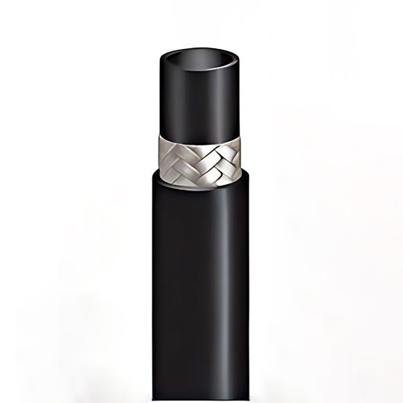
The hose provides a flexible high-pressure section between equipment such as the cementing unit, cement pump, pump manifold, cement manifold, treating line and cementing head. Its abrasion-resistant inner tube carries cement slurry, high-strength reinforcement supports the pressure load, and a heavy-duty outer cover protects the assembly during transport, installation and field operation.
Applications cover primary cementing, surface casing cementing, intermediate casing cementing, production casing cementing, liner cementing, squeeze cementing, remedial cementing, workover operations, well-integrity repair and selected cement-plug or P&A cementing programs on land and offshore rigs.
SGPE supports new projects, EPC packages and oilfield MRO requirements for 10K Cement Hose, 15K Cement Hose, 3 Inch Cement Hose, Fig. 1502 Cement Hose, High Pressure Cement Slurry Hose, Cement Pump Hose, Cement Manifold Flexible Hose, Offshore Cementing Hose, Custom Cement Hose and Replacement API 7K Cement Hose assemblies.
For a quotation, send:
Working Pressure + Hose I.D. + Overall Length + End A + End B + Quantity
Email: info@sgpe.com
Tel / WhatsApp: +86 186-1599-5239
API 7K Cement Hose Product Overview
An API 7K High Pressure Cement Hose forms part of the surface pressure system used during oil and gas well cementing.
The cementing unit mixes and pumps the cement slurry. From there, the high-pressure surface system carries the slurry toward the cementing head and into the well.
A typical flow path can include:
Cementing Unit → Cement Pump → Pump Manifold → Cement Manifold → Treating Line / Cement Hose → Cementing Head → Well
Much of the surface system uses rigid treating iron. A flexible hose becomes necessary where mobile pumping equipment connects with fixed piping, where equipment alignment changes from one job to another, or where the available layout does not suit an entirely rigid line.
The Cement Hose provides that flexible connection while maintaining the required pressure-containing flow path.
Depending on the cementing package, it can connect the cement pump to the pump manifold, the pump manifold to the cement manifold, the manifold to treating iron, or the high-pressure line toward the cementing head. Mobile cementing trucks, skid-mounted units, workover packages and offshore cementing systems all use similar connection principles.
The correct assembly is selected from the complete operating condition rather than pressure rating alone. Hose I.D., overall length, minimum bend radius, fluid temperature, cement slurry composition and both end connections all influence the final specification.
API 7K Cement Hose at a Glance
| Item | Typical Project Requirement |
|---|---|
| Product | API 7K Cement Hose |
| Alternative Terms | API 7K Cementing Hose, High Pressure Cementing Hose, Cement Slurry Hose |
| Applicable Standard | API Spec 7K |
| Flexible Specification Level | FSL 0 |
| Main Working Pressure | 10,000 PSI / 15,000 PSI |
| Metric Pressure | Approx. 69 MPa / 103.5 MPa |
| Common Hose I.D. | 2″, 2-1/2″, 3″ and other approved sizes |
| Primary Medium | Oilwell cement slurry |
| Internal Bore | Smooth-bore / full-flow construction |
| Common End Connections | Fig. 1002 / Fig. 1502 / Integral Flange |
| End Arrangement | M × F / M × M / F × F / mixed |
| Overall Length | Custom |
| Typical Installation | Pump manifold, cement manifold, cementing unit, cementing head |
| Project Environment | Land / offshore / workover |
| Procurement Type | New project / replacement / retrofit / MRO |
API 7K Cement Hose Technical Specifications
The following information provides a practical starting point for API 7K Cement Hose selection, engineering review and RFQ preparation.
| Technical Parameter | Typical Supply / Selection |
|---|---|
| Product | API 7K Cement Hose Assembly |
| Standard | API Spec 7K |
| FSL | FSL 0 |
| Working Pressure | 10,000 PSI / 15,000 PSI project configurations |
| Common Hose I.D. | 2″, 2-1/2″, 3″ and other approved sizes |
| Internal Bore | Smooth-bore / full-flow |
| Primary Service | High-pressure cement slurry transfer |
| Other Fluids | Compatible spacer, flush and cementing fluids where approved |
| Inner Tube | Abrasion-resistant synthetic rubber |
| Reinforcement | Multiple layers of high-tensile steel wire, steel cable or approved construction |
| Outer Cover | Oil-, abrasion-, ozone- and weather-resistant synthetic rubber |
| End Connections | Hammer Union, Integral Flange or project-specific oilfield connection |
| Common Union Figures | Fig. 1002 / Fig. 1502 where applicable |
| End Arrangement | Male × Female / Male × Male / Female × Female / mixed |
| Overall Length | Custom according to equipment layout |
| Minimum Bend Radius | Depends on hose size, pressure and construction |
| Hose O.D. | Design-specific |
| Assembly Weight | Design-specific |
| Operating Temperature | Depends on liner and hose construction |
| Pressure Testing | According to approved hose design and project requirements |
| Inspection | Visual, dimensional, connection and pressure-test inspection |
| Identification | Hose marking and serial traceability according to agreed scope |
| Typical Installation | Land rig, offshore rig, cementing skid, cementing unit or workover unit |
Note: Exact O.D., MBR, assembly weight, maximum length, operating temperature and test pressure depend on the selected hose construction. SGPE confirms the final values on the approved project datasheet.
Typical Engineering Reference for 10K and 15K Cement Hose
The figures below provide a preliminary reference based on established API 7K FSL 0 cement-hose constructions.
They are useful when estimating installation space, bend radius, assembly weight and handling requirements during the early project stage.
These values are industry engineering references rather than a universal SGPE specification table. Final dimensions and performance data follow the approved project datasheet.
10,000 PSI Cement Hose – Typical Industry Reference
| Hose I.D. | Working Pressure | Typical Test Pressure | Reference O.D. | Reference MBR | Reference Weight |
|---|---|---|---|---|---|
| 2″ / 51 mm | 10,000 PSI / 689 bar | 15,000 PSI / 1,034 bar | 108 mm / 4.25″ | 1.2 m / 3.93 ft | 20.7 kg/m |
| 2-1/2″ / 64 mm | 10,000 PSI / 689 bar | 15,000 PSI / 1,034 bar | 131 mm / 5.15″ | 1.2 m / 3.93 ft | 31.0 kg/m |
| 3″ / 76 mm | 10,000 PSI / 689 bar | 15,000 PSI / 1,034 bar | 142 mm / 5.59″ | 1.5 m / 4.92 ft | 34.9 kg/m |
| 4″ / 102 mm | 10,000 PSI / 689 bar | 15,000 PSI / 1,034 bar | 187 mm / 7.36″ | 1.4 m / 4.59 ft | 61.0 kg/m |
15,000 PSI Cement Hose – Typical Industry Reference
| Hose I.D. | Working Pressure | Typical Test Pressure | Reference O.D. | Reference MBR | Reference Weight |
|---|---|---|---|---|---|
| 2″ / 51 mm | 15,000 PSI / 1,034 bar | 22,500 PSI / 1,551 bar | 139 mm / 5.47″ | 1.4 m / 4.59 ft | 43.6 kg/m |
| 3″ / 76 mm | 15,000 PSI / 1,034 bar | 22,500 PSI / 1,551 bar | 167 mm / 6.57″ | 1.2 m / 3.93 ft | 57.6 kg/m |
Selected published bonded FSL 0 constructions can reach lengths of approximately 60 m, depending on hose design.
Published NBR-lined constructions commonly cover approximately -25°C to +100°C, while selected HNBR-lined designs can extend the upper temperature capability to around +121°C.
Final materials, dimensions, temperature capability and pressure-test requirements follow the approved hose design.
10,000 PSI and 15,000 PSI Cement Hose
10,000 PSI API 7K Cement Hose
A 10,000 PSI API 7K Cement Hose, also described as a 10K Cement Hose, 10000 PSI Cementing Hose or 69 MPa High Pressure Cement Hose, suits many surface cementing systems.
This pressure class is widely considered for casing and liner cementing, cement pump discharge, cement manifold connections and selected remedial or workover cementing operations.
Hose construction changes with bore size. A 2″, 2-1/2″ and 3″ hose can therefore have different O.D., minimum bend radius and assembly weight even when all three share the same working-pressure class.
A request for only:
3 Inch 10K Cement Hose
does not provide enough information for final selection.
A more useful specification is:
API 7K Cement Hose, FSL 0, 3″ I.D., 10,000 PSI WP, Fig. 1502 M/F, 10 m OAL, Qty. 2 pcs.
This gives the technical team enough information to begin reviewing the hose construction, end connections and installation.
15,000 PSI API 7K Cement Hose
A 15,000 PSI API 7K Cement Hose, or 15K Cement Hose / 15000 PSI Cementing Hose, serves systems that require a higher working-pressure class.
The additional reinforcement can have a significant effect on hose O.D., MBR, weight and handling.
A 15K assembly should therefore be reviewed against available rig or deck space, connection position and support method as well as the pressure requirement.
A typical specification may read:
API 7K Cement Hose, FSL 0, 3″ I.D., 15,000 PSI WP, Fig. 1502 M/F, required OAL, Qty. 2 pcs.
Related requirements include 15K Cement Manifold Hose, 15000 PSI Cement Slurry Hose, 15K Cementing Line Hose and Fig. 1502 High Pressure Cementing Hose.
API 7K Cement Hose Size, Length and Minimum Bend Radius
Size-related enquiries commonly involve 2 Inch Cement Hose, 2-1/2 Inch Cement Hose, 3 Inch Cement Hose, API 7K Cement Hose Size, Cement Hose Dimensions, Cement Hose MBR and Custom Length Cementing Hose.
The hose bore affects slurry velocity, flow capacity, pressure loss, outside diameter, connection size and assembly weight.
| Hose I.D. | Typical Selection Focus | Common Project Requirement |
|---|---|---|
| 2″ | Compact high-pressure connection | 10K / 15K applications |
| 2-1/2″ | Medium-bore cementing service | Selected project configurations |
| 3″ | Higher-flow cementing system | 10K / 15K applications |
| 4″ | Selected high-volume service | Typical 10K reference |
A larger I.D. is not automatically the best choice. Pump output, manifold bore, treating-line size, expected pressure loss and connection geometry need to work together.
Overall Length
Correct hose length allows the assembly to follow a smooth route without placing unnecessary load on the end fittings.
A hose that is too short can create axial tension or excessive bending near the couplings. A hose that is too long can create loops, additional weight and poor handling.
For replacement work, the existing overall length is often one of the most useful reference dimensions.
Minimum Bend Radius
The Cement Hose Minimum Bend Radius varies with hose I.D., working pressure and construction.
The approved MBR should be maintained throughout installation. Routing the hose below this limit can overstress the hose body and the areas close to the couplings.
Data Needed for Hose Routing
| Installation Data | Information Required | Why It Matters |
|---|---|---|
| End A Location | Pump / manifold / equipment | Defines first interface |
| End B Location | Manifold / treating line / cementing head | Defines second interface |
| Horizontal Distance | Field measurement | Helps determine OAL |
| Vertical Difference | Elevation offset | Affects hose route |
| Existing Hose OAL | Existing length | Replacement reference |
| Approved MBR | Hose datasheet | Protects hose structure |
| Available Clearance | Rig / skid layout | Prevents interference |
| End Orientation | Connection direction | Supports connection review |
| Equipment Movement | Fixed / limited movement | Affects hose routing |
| Handling Method | Supported / lifted | Important for heavier assemblies |
API 7K FSL 0 Cement Hose
For cement hose service under API Spec 7K, the applicable flexible specification level is FSL 0.
A clear procurement description should therefore include:
API 7K Cement Hose, FSL 0
rather than simply requesting an “API 7K Hose.”
This distinction matters because API 7K also covers Rotary, Vibrator and Jumper Hose applications used in drilling-fluid circulation systems.
A hose can share the same nominal pressure class with another oilfield hose and still be intended for a different service. Identifying both the application and FSL at the beginning of the enquiry reduces the risk of incorrect substitution.
High Pressure Cement Hose Construction
Abrasion-Resistant Inner Tube
The inner tube remains in direct contact with cement slurry.
Because oilwell cement contains suspended solids, the liner needs strong wear resistance. It also needs suitable compatibility with the fluids and temperatures expected during the cementing program.
Depending on the approved design, liner materials can include NBR-, HNBR- or other suitable synthetic-rubber compounds.
Spacer fluid, flush fluid, mix water and cement additives should also be considered where they contact the hose.
High-Strength Reinforcement
Multiple layers of high-tensile steel wire, steel cable or another approved reinforcement system carry the internal pressure load.
The reinforcement package changes with hose size and working pressure. Two hoses with the same nominal I.D. can therefore have different outside diameters, weights and bend radii.
Heavy-Duty Outer Cover
The outer cover protects the reinforcement during transportation, storage, installation and service.
A suitable oilfield cover provides resistance to abrasion, oil contamination, ozone, sunlight and normal outdoor exposure.
Where the installation creates severe mechanical contact, additional external protection can be included in the project review.
Materials and Temperature Reference
| Component / Condition | Typical Engineering Reference | Main Consideration |
|---|---|---|
| Inner Tube | NBR / HNBR-based or approved equivalent | Fluid compatibility |
| NBR Temperature | Approx. -25°C to +100°C on selected designs | Standard-temperature service |
| HNBR Temperature | Approx. -25°C to +121°C on selected designs | Higher-temperature service |
| Reinforcement | High-tensile steel wire / steel cable | Working pressure |
| Outer Cover | Heavy-duty synthetic rubber | Rig-site exposure |
| Bore | Smooth / full-flow | Cement slurry transfer |
| Length | Custom | Equipment layout |
Final material selection and temperature capability are confirmed for the approved hose construction.
API 7K Cement Hose End Connections
The end connectors form part of the complete pressure-containing hose assembly.
Hose I.D., working pressure, overall length and the End A / End B interfaces should therefore be specified together.
Typical mating equipment includes cementing pumps, pump manifolds, cement manifolds, treating iron, cementing skids and cementing heads.
| Connection | Typical Application | RFQ Information |
|---|---|---|
| Fig. 1002 Hammer Union | Selected cementing systems | Size + figure + gender |
| Fig. 1502 Hammer Union | High-pressure cementing | Size + figure + gender |
| Integral Flange | Cement skid / manifold | Size + pressure + standard |
| Male × Female | Common arrangement | End A + End B |
| Male × Male | Project-specific | Both connection details |
| Female × Female | Project-specific | Both connection details |
| Mixed Ends | Retrofit / replacement | Existing equipment interfaces |
A matching nominal size alone does not guarantee compatibility. Pressure class, union figure, gender and mating-equipment details also need to match.
Fig. 1002 Cement Hose
A Fig. 1002 Cement Hose uses a Fig. 1002 hammer-union connection where the actual union size, pressure rating and service suit the cementing system.
For quotation, identify the union size, figure number, connection gender, hose I.D., working pressure, overall length and opposite-end connection.
Fig. 1502 Cement Hose
A Fig. 1502 Cement Hose is a common requirement in high-pressure oilfield cementing systems.
Configurations can include Fig. 1502 Male × Female, Male × Male or Female × Female connections. A mixed-end assembly can also use Fig. 1502 on one end and an integral flange or another approved interface on the other.
Typical descriptions include 10K Fig. 1502 Cement Hose, 15K Fig. 1502 Cement Hose, Cement Hose with Fig. 1502 Hammer Union, Fig. 1502 Cementing Hose Assembly and Cement Manifold Hose with Fig. 1502 Ends.
Cement Hose with Integral Flange
Some cementing skids and manifolds use flanged interfaces instead of hammer unions.
For a Flanged Cement Hose or Cement Hose with Integral Flange, provide the flange size, pressure class, sealing interface and mating-equipment details.
A connection drawing or clear photograph is particularly useful for replacement projects.
Where Is an API 7K Cement Hose Installed?
Terms such as Cement Pump Hose, Cement Pump Discharge Hose, Cement Pump Manifold Hose, Cement Manifold Hose, Cementing Head Hose, Cementing Unit Hose and Cementing Truck Hose often describe where the flexible hose sits in the cementing system.
Cement Pump Discharge Hose
A Cement Pump Discharge Hose provides flexibility around the discharge side of the cement pump.
It can connect the pump with its discharge manifold or another section of the high-pressure cementing line.
Pump pressure, required flow, hose I.D. and both end connections are the main selection points.
Cement Pump Manifold Hose
A Cement Pump Manifold Hose can connect the pump manifold with the cement manifold or high-pressure treating line.
Both the pump-side and downstream interfaces should be reviewed before the final hose configuration is confirmed.
Cement Manifold Hose
A Cement Manifold Hose provides a flexible high-pressure connection around the cement manifold.
It can connect the pumping package to the manifold, or connect the manifold toward treating iron and the cementing head.
| Parameter | Information Required |
|---|---|
| Working Pressure | 10K / 15K or project-specific |
| Manifold Outlet | Actual connection size |
| Connection Type | Fig. 1002 / Fig. 1502 / flange / other |
| Hose I.D. | Required bore |
| Overall Length | Required OAL |
| End A | Complete specification |
| End B | Complete specification |
| Medium | Cement slurry / approved fluid |
| Temperature | Expected range |
| Layout | Equipment connection arrangement |
Cementing Head Hose
A Cementing Head Hose describes the flexible high-pressure line leading toward the cementing head.
Depending on the equipment package, the same requirement can also appear as a Cement Pump to Cementing Head Hose, Cement Manifold to Cementing Head Hose, Flexible Cementing Head Hose or Flexible Cementing Line to Cementing Head.
Cementing Unit and Cementing Truck Hose
A Cementing Unit Hose, Cementing Truck Hose or Cementing Skid Hose connects mobile pumping equipment with fixed wellsite pressure equipment.
In addition to pressure and hose bore, these installations require attention to skid or truck position, routing, assembly weight and available handling equipment.
API 7K Cement Hose Applications
An API 7K Cement Hose can support several surface cementing operations when the hose specification matches the actual pressure system.
| Application | Typical Hose Function | Main Selection Focus |
|---|---|---|
| Primary Cementing | Surface cement slurry transfer | Flow + pressure |
| Surface Casing Cementing | High-rate pumping | Flow capacity |
| Intermediate Casing Cementing | High-pressure cement transfer | Pressure + bore |
| Production Casing Cementing | Surface pumping connection | Pressure + ends |
| Liner Cementing | Flexible cementing connection | Routing |
| Squeeze Cementing | High-pressure remedial pumping | Pressure |
| Remedial Cementing | Mobile pumping connection | Existing interfaces |
| Workover Cementing | Service-unit connection | Length + connections |
| Recompletion | Surface cement pumping | Existing equipment |
| Cement Plug Placement | Cement transfer toward well | Pressure + flow |
| P&A Cementing | Surface barrier pumping | Equipment compatibility |
| Well Integrity Remediation | Repair cementing | Replacement matching |
Primary, Casing and Liner Cementing
During primary cementing, the hose can form part of the surface pumping spread for surface casing, intermediate casing, production casing and liner cementing.
Required pressure, flow bore and hose length vary with the cementing program and surface equipment.
Squeeze, Remedial and Workover Cementing
A Squeeze Cementing Hose, Remedial Cementing Hose or Workover Cementing Hose provides a flexible surface connection between mobile pumping equipment and existing pressure equipment.
These applications are often replacement-driven because much of the existing wellsite system remains in service.
Workover and recompletion projects can also require cement pumping for zonal isolation, casing repair and well-integrity work.
Cement Plug and P&A Cementing
Cement plugs are used for plugback, isolation and selected plug-and-abandonment operations.
Where the surface pumping system requires a flexible high-pressure section, the hose must match the pressure, fluid, temperature and connection requirements for that specific job.
The Cement Hose remains part of the surface cementing spread, not a downhole cementing tool.
Land and Offshore Cementing Hose Applications
| Project Environment | Typical Requirement | Main Selection Focus |
|---|---|---|
| Land Rig | Casing / liner cementing | Routing and length |
| Desert Oilfield | High ambient temperature | Temperature and UV |
| Cold-Region Rig | Low ambient temperature | Low-temperature flexibility |
| Offshore Platform | Integrated cementing package | Space and QA |
| Jack-Up Rig | Offshore cementing | Weight and routing |
| Semi-Submersible | Offshore drilling package | Equipment interfaces |
| Drillship | High-pressure cementing | Documentation and handling |
| Workover Rig | Remedial cementing | Replacement matching |
| Mature Field | Oilfield MRO | Existing connections |
| P&A Project | Cement plug work | System compatibility |
Land Rig Cementing Hose
Land-rig cementing frequently uses mobile cementing trucks or skids located beside the drilling rig.
The flexible line connects the mobile package to the cement manifold, treating line or cementing head.
The actual equipment position should determine the hose length rather than simply selecting the longest available assembly.
Offshore Cementing Hose
An Offshore Cementing Hose can serve fixed platforms, jack-up rigs, semi-submersibles, drillships and offshore workover units.
Offshore projects usually require closer review of hose weight, lifting, deck clearance, connection orientation, MBR, traceability and documentation.
High-Temperature and Cold-Weather Service
Temperature affects liner performance and hose flexibility.
Selected constructions can use HNBR-based liners for higher fluid temperatures, while cold-region projects require suitable low-temperature performance.
Provide the expected ambient and cementing-fluid temperatures whenever the service falls outside normal conditions.
Cement Slurry and Fluid Compatibility
Oilwell cement slurry is the primary medium, but other fluids can contact the hose during the cementing program.
| Fluid | Main Selection Issue |
|---|---|
| Oilwell Cement Slurry | Abrasion resistance |
| Spacer Fluid | Chemical compatibility |
| Flush Fluid | Liner compatibility |
| Mix Water | Fluid compatibility |
| Cement Additives | Chemical compatibility |
| Other Cementing Media | Technical review |
Unusual additives should be identified during the RFQ stage rather than assumed compatible with every hose liner.
API 7K Cement Hose vs. Other Oilfield Hoses
| Hose Type | Main Service | Typical Installation | FSL / Standard |
|---|---|---|---|
| API 7K Cement Hose | Cement slurry | Cementing unit / manifold / cementing head | FSL 0 |
| API 7K Rotary Hose | Drilling mud | Standpipe to swivel / Top Drive | FSL 1 / FSL 2 |
| API 7K Vibrator Hose | Drilling mud / pump vibration | Mud pump to standpipe manifold | FSL 1 / FSL 2 |
| API 7K Mud Jumper Hose | Drilling mud | Surface mud manifold / mud line | FSL 1 / FSL 2 |
| API 16C Choke & Kill Hose | Well-control fluid | BOP / choke / kill system | API 16C |
A Cement Hose carries cement slurry in the surface cementing system.
A Rotary Hose carries drilling mud toward the swivel or Top Drive. A Vibrator Hose works around the mud-pump discharge system, while a Mud Jumper Hose provides flexibility within the surface drilling-mud line.
These hoses can look similar and may share comparable pressure ratings, but their service duties differ.
API 7K Cement Hose vs. API 16C Choke and Kill Hose
An API 7K Cement Hose belongs to the well-cementing system.
An API 16C Choke and Kill Hose belongs to the well-control system around equipment such as the BOP, choke manifold and kill manifold.
A 10K or 15K working pressure does not make the two products interchangeable. The installation and service determine the correct hose family.
Replacement API 7K Cement Hose
A replacement enquiry does not always begin with a complete original datasheet.
In many MRO projects, the cementing unit, manifold and treating iron remain in service. The replacement hose therefore needs to match the installed system rather than only duplicate the nominal bore and working pressure.
| Existing Information | Why It Matters |
|---|---|
| Hose Marking | Helps identify original specification |
| API / FSL | Helps confirm hose family |
| Working Pressure | Confirms pressure class |
| Hose I.D. | Confirms bore |
| Overall Length | Supports dimensional matching |
| End A Photo | Identifies first connection |
| End B Photo | Identifies second connection |
| Hammer Union Figure | Confirms connection family |
| Male / Female Arrangement | Prevents mismatch |
| Equipment Model | Supports cross-checking |
| Drawing | Shows dimensions and interfaces |
| Previous Certificate | Provides technical reference |
| Installation Photo | Shows routing and clearance |
SGPE can use these details to identify missing information before preparing a Replacement Cement Hose quotation.
This approach suits Cement Manifold Replacement Hose, Cementing Unit Replacement Hose, Replacement Fig. 1502 Cement Hose, Replacement High Pressure Cementing Hose and Oilfield MRO Cement Hose enquiries.
Custom API 7K Cement Hose
Not every project uses a standard hose length or identical connections on both ends.
SGPE supports Custom API 7K Cement Hose requirements for new equipment, retrofit work and replacement projects.
A custom hose can use a project-specific OAL and different interfaces on End A and End B.
Project configurations can include Fig. 1002, Fig. 1502, integral flange, Male × Female, Male × Male, Female × Female and mixed-end arrangements.
Additional external protection, project marking, inspection requirements and documentation can also be defined during the RFQ stage.
For a custom assembly, an equipment drawing or clear photographs of the mating connections provide the best starting point.
Testing, Inspection and Traceability
A High Pressure Cementing Hose should be treated as a complete pressure-containing assembly that includes the hose body, couplings and end connections.
Depending on the agreed project scope, inspection can include dimensional verification, fitting inspection, visual examination, hydrostatic pressure testing and post-test checks.
| Inspection / Document | Purpose |
|---|---|
| Approved Technical Datasheet | Confirms final specification |
| Assembly Drawing | Confirms OAL and end connections |
| Component Verification | Checks hose and fitting arrangement |
| Dimensional Inspection | Confirms key dimensions |
| End-Fitting Inspection | Confirms connections |
| Visual Inspection | Checks finished condition |
| Hydrostatic Pressure Test | Verifies pressure integrity |
| Post-Test Inspection | Checks assembly after test |
| Pressure-Test Report | Records test results |
| Hose Marking | Supports identification |
| Serial Traceability | Supports future MRO |
| Third-Party Inspection | Supports project QA |
| Packing Documentation | Supports export shipment |
Any customer witness point, TPI requirement or special documentation request should be identified before production.
API 7K Cement Hose Installation and Maintenance
Before installation, verify the hose type, FSL, I.D., working pressure, end connections, union figure, overall length, minimum bend radius and identification.
The hose should follow a smooth natural curve between the pressure connections.
Avoid twisting, strong axial tension, sharp bends, contact with sharp structures and unsupported heavy end fittings.
During service, inspect the hose for severe abrasion, cuts, bulging, deformation, exposed reinforcement, damaged fittings, leakage or unusual movement.
After cementing, follow the approved flushing procedure so that cement residue does not harden inside the hose.
Inspection intervals and retirement criteria should follow the operating procedure and the requirements for the selected hose design.
API 7K Cement Hose Supplier for Oilfield Projects
Choosing an API 7K Cement Hose supplier, High Pressure Cementing Hose supplier or Oilfield Cement Hose supplier involves more than comparing nominal diameter and working pressure.
The proposed hose must match the real installation, required bore, overall length and mating equipment. Temperature, cementing fluid, bend radius, inspection requirements and project documentation also influence the final specification.
SGPE supports Cement Hose procurement for oil and gas operators, drilling contractors, cementing service companies, well-service companies, EPC contractors, equipment integrators, oilfield distributors and MRO teams.
For EPC and new-build projects, equipment layouts, datasheets and connection drawings can be reviewed before quotation.
For MRO work, existing hose markings, field photographs and connection details provide a practical starting point for replacement identification.
When comparing an API 7K Cement Hose manufacturer or supplier, buyers should focus on the suitability of the complete assembly rather than a generic catalogue description alone.
API 7K Cement Hose Price and Quotation
There is no single fixed API 7K Cement Hose price because pressure, bore, overall length, end connections and inspection scope can substantially change the assembly.
The same applies to a 10K Cement Hose Price, 15K Cement Hose Price, Fig. 1502 Cement Hose Price, Cement Manifold Hose Price, Cement Pump Hose Price, Custom Cement Hose Price or Replacement Cement Hose Quotation.
| Price Factor | Effect on Quotation |
|---|---|
| Working Pressure | Changes hose reinforcement and fittings |
| Hose I.D. | Changes hose construction |
| Overall Length | Changes material and weight |
| End A / End B | Changes connection configuration |
| Fig. 1002 / Fig. 1502 | Changes hammer-union requirements |
| Integral Flange | Adds connection requirements |
| Temperature | Can change liner selection |
| External Protection | Adds manufacturing scope |
| Testing | Changes QA scope |
| Third-Party Inspection | Adds inspection coordination |
| Documentation | Changes final dossier |
| Custom Configuration | Adds engineering review |
| Replacement Matching | Requires interface identification |
| Quantity | Affects production planning |
For a fast quotation, provide:
Working Pressure + Hose I.D. + Overall Length + End A + End B + Quantity
Why Choose SGPE for API 7K Cement Hose?
SGPE focuses on drilling, well-control, wellhead and high-pressure oilfield equipment. This gives our team a practical understanding of how a Cement Hose fits into the wider surface pressure system.
Application-Based Selection
The review starts with the actual hose location and the equipment connected to both ends rather than the pressure rating alone.
Pressure, Bore and Connection Matching
Working pressure, hose I.D., hammer-union figure, connection gender and mating equipment need to work together as one system.
Custom and Replacement Support
SGPE can review custom lengths, mixed-end configurations and existing hoses that need replacement even when the original datasheet is unavailable.
Land and Offshore Projects
Requirements can be reviewed for land rigs, offshore platforms, jack-ups, semi-submersibles, drillships and workover units.
Inspection and Documentation
Hydrostatic testing, third-party inspection, customer witness points and project documentation can be included in the agreed supply scope.
Related SGPE Oilfield Hose and Cementing Equipment
API 7K Cement Hose often forms part of a larger drilling or cementing package.
Related SGPE products include API 7K Rotary Hose, API 7K Vibrator Hose, API 7K Mud Jumper Hose, API 16C Choke and Kill Hose, Cement Manifold, High Pressure Treating Iron, Fig. 1002 Hammer Union, Fig. 1502 Hammer Union, Cementing Head, API 6A Gate Valve and high-pressure wellhead equipment.
Where dedicated product pages exist, these products should be internally linked so buyers can move naturally between the hose, manifold, treating-line and wellhead equipment used in the same project.
API 7K Cement Hose RFQ Data Sheet
| RFQ Item | Information to Provide |
|---|---|
| Product | API 7K Cement Hose |
| Quantity | Required quantity |
| Application | Casing / liner / remedial / workover / P&A / other |
| FSL | FSL 0 |
| Working Pressure | 10K / 15K |
| Hose I.D. | Required internal diameter |
| Overall Length | Required OAL |
| End A | Complete connection specification |
| End B | Complete connection specification |
| Union Figure | Fig. 1002 / Fig. 1502 / other |
| End Arrangement | M/F / M/M / F/F |
| Flange Details | If applicable |
| Cementing Fluid | Cement slurry / spacer / other |
| Fluid Temperature | Minimum / maximum |
| Ambient Temperature | Minimum / maximum |
| Installation | Land / offshore |
| Rig Type | Land rig / platform / jack-up / semi-sub / drillship |
| Minimum Bend Radius | If project-specific |
| External Protection | If required |
| Inspection | Customer / TPI requirements |
| Documentation | Required records / certificates |
| Existing Hose Marking | For replacement |
| Existing Hose Photos | For replacement |
| Equipment Drawing | If available |
| Project Destination | Country / project |
If complete data is not yet available, start with:
Working Pressure + Hose I.D. + Overall Length + End A + End B + Quantity
Frequently Asked Questions About API 7K Cement Hose
1. What is an API 7K Cement Hose and where is it used?
An API 7K Cement Hose is a flexible high-pressure hose assembly that transfers cement slurry through the surface pressure system during oil and gas well cementing. It connects equipment such as the cementing unit, cement pump, pump manifold, cement manifold, high-pressure treating line and cementing head.
The oilfield industry also refers to this product as an API 7K Cementing Hose, High Pressure Cementing Hose, Oilfield Cement Hose, Oil Well Cementing Hose, Cement Slurry Hose, Surface Cementing Hose or Cement Manifold Hose.
Typical applications include surface casing cementing, intermediate casing cementing, production casing cementing, liner cementing, squeeze cementing, remedial cementing and workover operations. On land rigs, the hose often connects a mobile cementing truck or skid with fixed rig-side equipment. Offshore cementing systems can install it on platforms, jack-up rigs, semi-submersibles and drillships.
2. What does FSL 0 mean for an API 7K Cement Hose?
API Spec 7K assigns FSL 0 to cement hose applications. A clear purchase specification should therefore state API 7K Cement Hose, FSL 0 rather than simply “API 7K Hose.”
This distinction matters because API 7K also covers Rotary Hose, Vibrator Hose and Jumper Hose applications in drilling-fluid circulation systems. These hoses operate at different positions on the drilling rig and follow different FSL selection requirements.
Two hoses can share a similar bore and working pressure but still serve completely different applications. When the RFQ clearly states API 7K + Cement Hose + FSL 0, the supplier can immediately identify the requirement as high-pressure cement slurry service rather than drilling-mud circulation.
3. What working pressures are commonly required for API 7K Cement Hose?
High-pressure cementing projects commonly specify 10,000 PSI or 15,000 PSI API 7K Cement Hose assemblies. A 10K Cement Hose suits many surface cementing systems, while a 15K Cement Hose handles projects with higher pressure requirements.
Working pressure affects much more than the number marked on the hose. It influences the reinforcement structure, outside diameter, minimum bend radius, assembly weight and end-fitting design. For example, a 3″ 15K hose can require considerably more installation space and handling support than a 3″ 10K hose.
For casing cementing, liner cementing, cement manifold service or cement pump discharge applications, project engineers should check the required pressure against the complete surface system. The hose, hammer unions, flanges, manifolds and mating equipment all need compatible pressure ratings.
4. What sizes are commonly used for 10K and 15K Cement Hose?
Common oilfield enquiries specify 2 Inch, 2-1/2 Inch and 3 Inch Cement Hose assemblies. Some projects also require other approved sizes according to flow rate, pressure class and hose construction.
Hose I.D. directly affects cement slurry velocity, pressure loss, outside diameter, minimum bend radius and assembly weight. A larger bore therefore does not automatically improve the cementing system. Engineers should consider cement pump output, manifold bore, treating-line size and end connections together.
A 3 Inch API 7K Cement Hose is a common high-flow requirement, but manufacturers do not offer every size in every pressure class. Before production, the project team should confirm the complete combination of hose I.D. + 10K or 15K working pressure + overall length + end connections.
5. What are the typical test pressures for 10K and 15K Cement Hose?
Published API 7K FSL 0 hose constructions commonly show approximately 15,000 PSI test pressure for a 10,000 PSI working-pressure hose and approximately 22,500 PSI test pressure for a 15,000 PSI working-pressure hose.
These figures provide useful preliminary engineering references, but no single test-pressure table applies to every hose design. The hose construction, applicable specification and approved project datasheet determine the final hydrostatic test requirement.
For each order, SGPE reviews the selected hose configuration and confirms the applicable pressure-test requirement. If the project requires customer witness, third-party inspection or a formal pressure-test report, the buyer should state these requirements during the RFQ stage so SGPE can include them in the inspection and documentation scope.
6. Can API 7K Cement Hose use Fig. 1002 or Fig. 1502 hammer unions?
Yes. SGPE can provide Fig. 1002 Cement Hose and Fig. 1502 Cement Hose configurations when the union size, pressure rating and service match the complete hose assembly.
High-pressure cementing systems frequently use Fig. 1502 hammer union ends, especially around cement pump discharge lines, cement manifolds and other high-pressure surface connections. Depending on the equipment layout, the hose can use Male × Female, Male × Male, Female × Female or mixed-end arrangements.
The hammer-union figure alone does not define the correct hose. A complete RFQ should also state the connection size and gender, hose I.D., working pressure and overall length. If one side of the system uses a different interface, SGPE can review a custom assembly with Fig. 1502 on one end and an integral flange or another approved oilfield connection on the other.
7. What is a Cement Manifold Hose and where is it installed?
A Cement Manifold Hose provides a flexible high-pressure connection around the cement manifold section of the surface pumping system. Depending on the wellsite layout, it can connect the cementing unit or pump with the cement manifold, connect the manifold with high-pressure treating iron, or form the flexible section leading toward the cementing head.
The correct Cement Manifold Hose depends on the manifold working pressure, outlet size, connection type, hose bore and overall length. Common project requirements include 10K Cement Manifold Hose, 15K Cement Manifold Hose and Fig. 1502 Cement Manifold Hose.
For replacement work, buyers can send the existing hose marking, overall length, working pressure and clear photographs of the manifold connection and opposite hose end. These details help SGPE match the new assembly with equipment already operating in the field.
8. What is the difference between a Cement Pump Hose and a Cement Manifold Hose?
A Cement Pump Hose or Cement Pump Discharge Hose normally works around the discharge side of the cementing pump, while a Cement Manifold Hose provides flexibility around the cement manifold.
In a typical surface cementing spread, the Cement Pump Hose can connect the pump with its discharge manifold or another high-pressure line. The Cement Manifold Hose can then connect the manifold toward treating iron or the cementing head.
Both assemblies can use similar high-pressure hose construction, but the installation point determines the final specification. Project engineers should select working pressure, flow bore, overall length and end connections according to the equipment on each side rather than the product name alone.
This distinction becomes especially important when replacing hoses on cementing trucks, skid-mounted cementing units, offshore cementing packages and workover equipment.
9. Can an API 7K Cement Hose replace a Rotary Hose, Vibrator Hose or Mud Jumper Hose?
No. These hoses serve different oilfield applications even when they look similar or share the same nominal bore and pressure class.
An API 7K Cement Hose carries cement slurry through the surface cementing system and uses FSL 0. An API 7K Rotary Hose carries drilling mud between the standpipe and swivel or Top Drive. A Vibrator Hose normally connects the mud pump discharge system with the standpipe manifold, while a Mud Jumper Hose provides flexibility within the surface drilling-mud system.
Before ordering a replacement, buyers should confirm the fluid, installation point and FSL requirement. Selecting a hose only by size and working pressure can lead to the wrong product family.
For MRO procurement, SGPE recommends sending the existing hose marking together with a photograph that clearly shows where the hose connects within the rig system.
10. Is API 7K Cement Hose the same as API 16C Choke and Kill Hose?
No. API 7K Cement Hose and API 16C Choke and Kill Hose serve different oilfield pressure systems.
API 7K Cement Hose transfers high-pressure cement slurry during well cementing. Typical connection points include cementing units, pump manifolds, cement manifolds and cementing heads.
An API 16C Choke and Kill Hose works within the well-control system and connects equipment around the BOP stack, choke manifold and kill manifold.
Both hose families can have 10K or 15K pressure ratings, so working pressure alone cannot identify the correct product. If the existing hose connects directly to a choke line, kill line or BOP-related component, the buyer should verify the API 16C requirement before ordering a replacement.
11. Can SGPE quote a Replacement API 7K Cement Hose from photographs?
Yes. SGPE regularly reviews Replacement API 7K Cement Hose and oilfield MRO enquiries even when the buyer does not have the original manufacturer datasheet.
Start by sending a clear photograph of the complete hose together with the hose marking, working pressure, hose I.D. and overall length. Clear photographs of End A and End B help SGPE identify the hammer-union figure, flange type and male or female connection arrangement.
The equipment model, original drawing, previous pressure-test certificate and installation photograph can provide additional reference when available.
This approach works well for Replacement Fig. 1502 Cement Hose, Cement Manifold Replacement Hose, Cementing Unit Replacement Hose, Cement Pump Hose replacement and other high-pressure cementing hose MRO projects where the surrounding equipment remains in service.
12. What information should I send for an API 7K Cement Hose quotation?
For an accurate API 7K Cement Hose price and quotation, provide the working pressure, hose I.D., overall length, End A, End B and required quantity.
A clear RFQ can read:
API 7K Cement Hose, FSL 0, 3″ I.D., 15,000 PSI WP, Fig. 1502 M/F, 12 m OAL, Qty. 2 pcs.
For a new cementing package or EPC project, also provide the cementing fluid, operating temperature, rig type, equipment layout and inspection requirements when available. Offshore projects can also require additional traceability, lifting arrangements and project documentation.
For a replacement hose, send the existing hose marking, overall length and clear photographs of both end connections. Even without the original datasheet, these details usually give SGPE enough information to begin the technical review and prepare the corresponding Replacement API 7K Cement Hose quotation.
Request an API 7K Cement Hose Quotation from SGPE
SGPE supplies API 7K Cement Hose assemblies for land and offshore cementing systems, including 10K and 15K Cement Hose, Fig. 1002 and Fig. 1502 Cement Hose, Cement Manifold Hose, Cement Pump Discharge Hose, Custom Cement Hose and Replacement API 7K Cement Hose.
Our hoses support casing and liner cementing, remedial cementing, workover operations, well-integrity projects and other high-pressure surface cementing applications.
For a new project, please provide the working pressure, hose I.D., overall length, End A, End B and quantity. For replacement requirements, send the existing hose marking, overall dimensions and clear photographs of both end connections.
Email: info@sgpe.com
Tel / WhatsApp: +86 186-1599-5239