Description
High Pressure Frac Hose for Frac Pumps, Manifolds & Pressure Pumping Systems
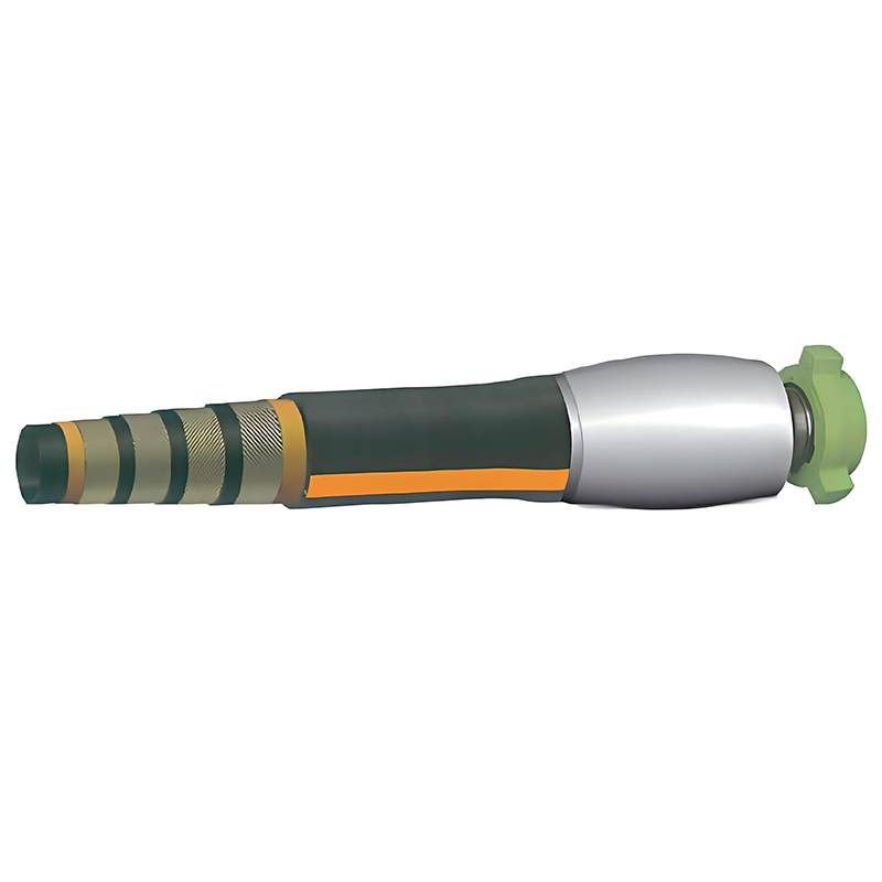
SGPE supplies High Pressure Frac Hose assemblies for hydraulic fracturing, pressure pumping, well stimulation, acidizing and abrasive proppant service.
Installed at selected flexible points in a frac spread, the hose can connect frac pumps, pump discharge systems, missile manifolds, frac manifolds, zipper manifolds, stimulation skids and other high-pressure flowline equipment.
A correctly selected High Pressure Flex Hose accommodates pump vibration, small equipment offsets and controlled movement while maintaining the pressure and flow capacity required by the pumping system. In suitable positions, it can also simplify rigid flowline transitions and make repeated field rig-up easier to manage.
Typical project configurations include 10,000 PSI and 15,000 PSI working pressure, while selected designs can be reviewed for 20,000 PSI well stimulation service. Common hose I.D.s range from approximately 2 in. to 6 in., depending on pressure class, pumping rate, fluid, hose construction and end connection.
Available interfaces include Fig. 1502 Hammer Unions, Fig. 2002 connections, high-pressure hubs, integral flanges, fixed flanges and rotating flanges.
Depending on the installation, procurement teams may also describe this product as a Hydraulic Fracturing Hose, Oilfield Frac Hose, Pressure Pumping Hose, 15K Frac Hose, Fig. 1502 Frac Hose, High Flow Frac Hose, Frac Pump Discharge Hose, Pump-to-Manifold Frac Hose, Frac Manifold Hose, Flexible Treating Line, Well Stimulation Hose or Replacement Frac Hose.
With more than 20 years of oilfield equipment experience, SGPE supports requirements ranging from one replacement assembly to custom-length hoses, matched hose sets, OEM equipment packages, frac fleet MRO spares and EPC project supply.
Email: info@sgpe.com
Tel / WhatsApp: +86 186-1599-5239
High Pressure Frac Hose Technical Specifications
| Parameter | Typical / Available Configuration |
|---|---|
| Product | High Pressure Frac Hose |
| Product Form | Complete Frac Hose Assembly |
| Main Service | Hydraulic Fracturing / Pressure Pumping / Well Stimulation |
| Typical Working Pressure | 10,000 PSI / 15,000 PSI |
| High-Pressure Option | Selected 20,000 PSI Configurations |
| Typical Hose I.D. | Approx. 2 in. to 6 in. |
| Hose O.D. | According to I.D., Pressure Class and Reinforcement |
| Overall Length | Custom / Project Specific |
| Common 15K Connection | Fig. 1502 Hammer Union |
| Other Connections | Fig. 2002 / Hub / Integral Flange / Fixed Flange / Rotating Flange |
| Typical Media | Slickwater, Gelled Fluid, Frac Slurry, Proppant Slurry |
| Acidizing Service | Subject to Chemical Compatibility Review |
| Inner Liner | Abrasion- and Stimulation-Fluid Compatible |
| Reinforcement | Multi-Layer High-Tensile Reinforcement |
| Outer Cover | Abrasion-, Oil-, Weather- and Handling-Resistant |
| External Protection | Guard / Armor / Project-Specific Protection |
| Minimum Bend Radius | According to Hose Construction and I.D. |
| Maximum Flow Rate | According to Bore, Fluid and Approved Design |
| Full-Bore Option | Subject to Selected Hose Design |
| Temperature | According to Selected Liner and Construction |
| Pressure Cycling | According to Approved Operating Duty |
| Hydrostatic Test | According to Approved Hose Design and Procedure |
| Customer Witness | Available When Required |
| Third-Party Inspection | Available When Specified |
| Documentation | TDS / Inspection / Hydrostatic Test Records |
| End A / End B | Same or Mixed Connections Available |
Important: Not every hose I.D. can use every pressure class or connection. Final O.D., weight, minimum bend radius, temperature range, flow capacity and test pressure must follow the approved SGPE project datasheet.
What Is a High Pressure Frac Hose?
A High Pressure Frac Hose is a reinforced flexible pressure-containing assembly used to transfer stimulation fluid during hydraulic fracturing and other high-pressure well-treatment operations.
A frac spread normally combines high-horsepower pumps with discharge manifolds, missile manifolds, frac manifolds, zipper manifolds and rigid treating iron. Hammer unions, swivel joints, integral pup joints and plug valves connect the pressure-containing flowline before the fluid reaches the frac tree and wellhead.
Rigid treating iron remains the primary flow path in many systems. Mobile pumping units and fixed manifolds, however, are not always positioned with perfect alignment in the field. Pump vibration, equipment movement and repeated rig-up can also introduce mechanical loads into a completely rigid arrangement.
A flexible frac hose provides controlled movement at selected interfaces. Typical locations include frac pump discharge lines, pump-to-missile manifold connections, pump-to-frac manifold connections, manifold crossovers, zipper manifold interfaces and pressure-pumping skid connections.
Hydraulic fracturing combines high pressure, high flow velocity, abrasive solids and repeated pressure cycles. Selecting a hose from PSI alone is therefore not enough.
The complete operating condition should include internal bore, maximum pumping rate, stimulation fluid, proppant loading, temperature, minimum bending radius, overall length and both end connections.
High Pressure Frac Hose Supplier for New Projects, OEM and MRO
A frac hose normally has to match equipment that is already defined by the project.
For new frac equipment, SGPE can review a datasheet, BOQ, pump arrangement, manifold drawing or overall equipment layout. For an existing fleet, the review can often begin from a hose nameplate, body marking, original part number, field photographs and connection dimensions.
SGPE supports custom frac hose assemblies, replacement hoses, OEM equipment packages, EPC procurement, brownfield upgrades, batch orders and frac fleet MRO spare packages.
This approach helps avoid a common purchasing problem: selecting a hose because its visible connection and PSI rating appear correct while overlooking its internal bore, effective fitting bore, flow requirement, MBR or fluid compatibility.
10K, 15K and 20K High Pressure Frac Hose
| Pressure Class | Typical Application | Connection Considerations |
|---|---|---|
| 10,000 PSI | Selected fracturing, pressure-pumping, acidizing and workover stimulation service | Complete system must be compatible with 10K service |
| 15,000 PSI | Frac pump discharge, pump-to-manifold, frac manifold and high-pressure stimulation | Fig. 1502 commonly used |
| Selected 20,000 PSI | Deep-well and severe-service pressure pumping | Fig. 2002, high-pressure hub or flange where applicable |
15,000 PSI Frac Hose
The 15,000 PSI Frac Hose, often specified as a 15K Frac Hose or 15K Flexible Frac Hose, is an important configuration in modern pressure-pumping systems.
Many 15K systems use Fig. 1502 Hammer Union connections. A 15K hose may connect a frac pump to a missile manifold, serve a frac manifold interface or form part of a high-pressure stimulation package.
Similar configurations are used in shale stimulation, multi-stage fracturing, slickwater pumping, proppant service and selected acid-fracturing operations.
The final test pressure, MBR, maximum flow, hose weight and fitting arrangement depend on the selected bore and complete hose construction.
Selected 20,000 PSI Frac Hose
A 20,000 PSI High Pressure Frac Hose requires a complete hose assembly designed for the higher pressure.
Depending on the approved design, the connection may use Fig. 2002, a high-pressure hub or a suitable 20K flange. Higher-pressure service can also change the reinforcement, assembly weight and required bending envelope.
A higher-rated end fitting alone does not convert a 15K hose into a 20K hose.
Common 10K and 15K Frac Hose Buying Configurations
The following descriptions are representative of the way frac hose requirements are commonly written in technical RFQs.
| Typical RFQ Configuration | Typical Application |
|---|---|
| 2 in. / 2-1/2 in. 10K Frac Hose | Compact pressure-pumping or stimulation connection |
| 2 in. / 2-1/2 in. 15K Fig. 1502 Frac Hose | High-pressure pump or manifold connection |
| 3 in. 15K Fig. 1502 Frac Hose | Frac pump discharge and pump-to-manifold service |
| 4 in. 15K Fig. 1502 Frac Hose | Higher-flow frac manifold and stimulation service |
| 3 in. / 4 in. 15K Hub-End Frac Hose | OEM skid or manifold interface |
| Large-Bore 15K Flanged Frac Hose | High-flow fixed-equipment connection |
| Selected 20K Fig. 2002 / Hub / Flanged Hose | Severe-service pressure-pumping project |
| Custom Mixed-End Frac Hose | Existing equipment or replacement application |
Field RFQs sometimes shorten a requirement to “15K 1502 hose”, “1502 hose” or “3 inch 1502 hose.” These descriptions are not complete enough for final selection.
A useful purchasing specification should identify the hose I.D., working pressure, overall length, End A and End B.
15K Frac Hose Size, Flow and MBR Engineering Reference
The following values provide a preliminary industry reference for common 15,000 PSI flexible frac hose designs.
They can support early sizing and layout discussions but do not represent guaranteed SGPE product values.
| Nominal Hose I.D. | Published Flow Reference | Published MBR Reference | Common Connection Examples |
|---|---|---|---|
| 2 in. | Approx. 9–13 bbl/min | Approx. 24–36 in. | 3 in. Fig. 1502 |
| 2-1/2 in. | Approx. 18–21 bbl/min | Approx. 28–39 in. | 3 in. Fig. 1502 |
| 3 in. | Approx. 26–29 bbl/min | Approx. 39–43 in. | 3 in. Fig. 1502 / 3-1/16 in. 15K Flange |
| 3-1/2 in. | Approx. 36–40 bbl/min | Approx. 43–52 in. | 4 in. Fig. 1502 |
| 4 in. | Approx. 47–56 bbl/min | Approx. 47–52 in. | 4 in. Fig. 1502 / 4-1/16 in. 15K Flange |
| 5 in. | Approx. 84–120 bbl/min | Approx. 51–63 in. | 5-1/8 in. 15K Rotating Flange |
| 6 in. | Approx. 120–140 bbl/min | Approx. 56–66 in. | 7-1/16 in. 15K Rotating Flange |
Reference Note: These ranges are compiled from publicly available technical literature for high-pressure frac hose designs and are provided for preliminary engineering comparison only. Flow capacity, MBR, temperature, weight and test requirements vary by design. Final SGPE values shall follow the approved project TDS.
3 Inch and 4 Inch 15K High Flow Frac Hose
A High Flow Frac Hose cannot be selected from connection size alone.
A smaller internal bore increases fluid velocity and can increase pressure loss, turbulence and erosion. Increasing the bore can improve hydraulic performance, but it also increases assembly weight, pressure thrust, minimum bending radius and support requirements.
A 3 in. 15K Frac Hose is commonly considered for frac pump discharge, pump-to-manifold and manifold applications where the system needs a practical balance between flow capacity, hose weight and routing space.
A 4 in. 15K Frac Hose can suit higher-volume stimulation systems that require a larger flow path. Large-bore 5 in. and 6 in. hoses require considerably more installation space and mechanical support.
Final sizing should consider:
Hose I.D. + Maximum Pumping Rate + Working Pressure + Fluid + Proppant Concentration + Installation Geometry
Full Bore and Smooth Bore Frac Hose
A Full Bore Frac Hose or Smooth Bore Frac Hose uses an internal flow path designed to minimize unnecessary restrictions through the hose body and end fittings.
This becomes important in high-rate pressure pumping. Abrupt restrictions can increase turbulence and pressure loss, while abrasive proppant passing through the same area can accelerate localized liner wear.
The effective bore through the fittings should therefore be considered together with the nominal hose I.D.
15,000 PSI Fig. 1502 Frac Hose
A 15,000 PSI Fig. 1502 Frac Hose is one of the most common flexible high-pressure configurations used in oilfield pressure-pumping systems.
Fig. 1502 connections can interface with compatible frac manifolds, missile manifolds, treating iron, frac pump discharge equipment, plug valves, swivel joints, integral pup joints and stimulation skids.
The connection provides a compact field interface and supports efficient rig-up and rig-down.
One important point is that the hose I.D. and Fig. 1502 connection size do not always match.
A complete purchasing description might read:
3 in. High Pressure Frac Hose × 15,000 PSI WP × 3 in. Fig. 1502 Male × Female × 20 ft OAL
For another installation, the same hose body may require a Fig. 1502 connection on one end and a hub or flange on the other.
SGPE can therefore review Fig. 1502 × Fig. 1502, Fig. 1502 × Hub, Fig. 1502 × Flange and other mixed-end frac hose assemblies.
High Pressure Frac Hose Connection Options
| End A | End B | Typical Application |
|---|---|---|
| Fig. 1502 Male | Fig. 1502 Female | Standard 15K frac hose connection |
| Fig. 1502 | Fig. 1502 | Pump / treating-line connection |
| Fig. 1502 | High-Pressure Hub | Frac manifold or OEM skid interface |
| Fig. 1502 | Flange | Union-to-fixed equipment transition |
| Hub | Hub | Compact manifold interface |
| Hub | Flange | OEM equipment transition |
| Flange | Flange | Large-bore high-flow connection |
| Fig. 2002 | Fig. 2002 | Selected 20K pressure-pumping service |
For a hub-end frac hose, the interface review covers the hub profile, effective bore, pressure rating, clamp system, seal interface and mating dimensions.
For a flanged frac hose, the flange size, pressure class, sealing interface and bolt-hole arrangement must match the connected equipment. Integral, fixed and rotating flange arrangements can be considered according to the installation.
High Pressure Frac Hose Construction
Abrasion-Resistant Inner Liner
The inner liner is directly exposed to the stimulation fluid.
Depending on the job, the hose may carry slickwater, gelled frac fluid, natural frac sand slurry, ceramic proppant slurry, resin-coated proppant or selected acidizing fluids.
Proppant can create severe internal wear, particularly where high velocity combines with tight bends or abrupt flow transitions.
For abrasive service, liner compatibility has to be considered together with the internal bore and actual pumping duty.
High-Tensile Reinforcement
The reinforcement contains internal pressure while allowing the assembly to retain controlled flexibility.
Its design influences working pressure, pressure-cycle capability, hose weight, fatigue performance, hydrostatic testing and minimum bending radius.
Outer Protection
Field hoses can be exposed to sand, mud, oil, water, UV, ground abrasion and repeated contact with other high-pressure flowline equipment.
Selected constructions can use guards, armor or other project-specific external protection where additional mechanical protection is required.
Bonded Frac Hose vs. Crimped Frac Hose
A Bonded Frac Hose generally uses a bonded or mechanically integrated hose-end system, while a Crimped Frac Hose uses an approved mechanical crimp arrangement.
Neither construction automatically provides a higher working pressure.
Actual capability depends on the complete hose design, including its liner, reinforcement and end-fitting retention system.
Frac Hose for Proppant, Slickwater and Acid Service
A Proppant Frac Hose or Frac Sand Hose operates in one of the most abrasive parts of a pressure-pumping system.
Natural frac sand, silica sand, ceramic proppant and resin-coated proppant can continuously attack the inner liner. Wear normally increases around tight bends, end-fitting transitions and other areas where excessive velocity creates turbulence.
Pressure rating alone therefore does not confirm suitability for abrasive slurry service.
The hose should be evaluated according to I.D., pumping rate, proppant type, concentration, working pressure, MBR and expected pumping duty.
A Slickwater Frac Hose can face similar erosion concerns when low-viscosity fluid is pumped at high rate while carrying abrasive solids.
Selected Acidizing Frac Hose constructions can support acid-based stimulation when the liner and end-fitting materials are compatible with the chemical environment. Acid type, concentration, additives, working pressure, temperature and expected exposure duration should be provided before final selection.
High Pressure Frac Hose Applications
Frac Pump Discharge Hose
A Frac Pump Discharge Hose provides controlled flexibility downstream of the frac pump, where the assembly may experience high flow, vibration, pressure pulsation and repeated pressure cycles.
Correct routing is important because the hose needs to accommodate movement without creating an excessive bend or unnecessary internal restriction.
Pump-to-Manifold Frac Hose
A Pump-to-Manifold Frac Hose connects selected pumping equipment to a missile, discharge or frac manifold while accommodating small positioning differences.
This is particularly useful on frac spreads where pumping units are repeatedly rigged up, moved and repositioned between jobs or pad locations.
Frac Manifold and Zipper Manifold Service
A Frac Manifold Hose can provide a flexible interface at selected positions around high-pressure frac and zipper manifolds.
The hose must match the manifold working pressure, effective bore, maximum flow requirement and connection geometry.
Multi-well pads, zipper-frac layouts and other high-rate completion programs can place additional emphasis on flow capacity and repeated pressure cycling.
Shale, Multi-Stage and Simul-Frac Operations
Flexible frac hose assemblies may be used in horizontal shale wells, multi-stage fracturing, tight oil development, tight gas stimulation and selected high-rate or simul-frac layouts.
The actual suitability depends on the approved hose design and the pressure, flow, proppant, routing and duty-cycle requirements of the project.
Re-Fracturing and Well Stimulation
Selected assemblies can also support re-fracturing, matrix acidizing, acid fracturing, remedial stimulation and other high-pressure well-treatment operations.
Fluid chemistry and operating duty must be reviewed before the hose is confirmed for these services.
High Pressure Frac Hose vs. Traditional Treating Iron
| Item | High Pressure Frac Hose | Traditional Treating Iron |
|---|---|---|
| Construction | Flexible Reinforced Assembly | Rigid Steel Flowline |
| Typical Role | Selected Flexible Connection | Primary Rigid Flowline |
| Flexibility | High | Low |
| Alignment Tolerance | Better | Requires Accurate Alignment |
| Vibration Accommodation | Better | Limited |
| Bend Control | Minimum Bend Radius | Elbows / Swivel Joints |
| Common Connections | Fig. 1502 / Hub / Flange | Hammer Union / Hub |
| Abrasive Service | Suitable Liner Required | Erosion-Resistant Steel Required |
| Rig-Up | Can Simplify Selected Interfaces | Built from Multiple Rigid Components |
| Length | Custom Hose Assembly | Individual Iron Sections |
A Frac Iron Replacement Hose can simplify selected parts of a rigid pressure-pumping layout, but it should not automatically replace the complete treating-iron flowline.
Many frac systems use rigid iron through the primary pressure path and flexible hose only where movement, vibration or alignment tolerance provides a clear benefit.
High Pressure Frac Hose vs. API 16C and API 7K Hoses
A High Pressure Frac Hose primarily serves completion and stimulation, including hydraulic fracturing, pressure pumping, proppant service and acidizing.
An API 16C Choke and Kill Hose serves drilling well-control systems around BOP, choke and kill equipment.
An API 7K Rotary Hose serves drilling-fluid circulation.
These hose families can share similar pressure classes or connection styles, but they are not automatically interchangeable because the media, movement, pressure cycling and applicable technical requirements differ.
Some procurement searches use the phrase API 7K Frac Hose. That wording alone does not establish API 7K compliance.
When a project requires API 7K or another specific standard, the requirement should be stated clearly in the RFQ so the applicable design and documentation can be confirmed.
Minimum Bend Radius and Correct Frac Hose Length
Every High Pressure Frac Hose has an approved Minimum Bending Radius (MBR).
Operating below that radius places excessive stress on the liner and reinforcement and can increase the risk of kinking, localized wear, reinforcement distortion or reduced hose life.
Overall length matters just as much.
A hose that is too short can remain under tension or form an excessively tight bend. A hose that is too long can create unnecessary loops, dragging or uncontrolled movement.
Before the final OAL is confirmed, the installation should be reviewed for End A-to-End B distance, horizontal and vertical offset, expected movement, connection orientation and available bending space.
How to Select the Right High Pressure Frac Hose
| Selection Item | Information Required |
|---|---|
| Working Pressure | 10K / 15K / 20K / Other |
| Hose I.D. | Required Internal Bore |
| Maximum Pumping Rate | bbl/min, gpm, L/min or m³/min |
| Fluid | Slickwater / Gel / Slurry / Acid |
| Proppant | Type and Maximum Concentration |
| Overall Length | Required OAL |
| End A | Connection Type and Size |
| End B | Connection Type and Size |
| Temperature | Minimum / Maximum |
| Installation Position | Pump / Manifold / Zipper / Wellhead |
| Available Space | Layout / Offset / Bending Envelope |
| Inspection | Hydrotest / Customer Witness / TPI |
| Documentation | TDS / Test Records / ITP Requirements |
These parameters need to be considered together.
A 15K hose can still be unsuitable if its bore is too small for the required pumping rate, its liner is incompatible with the stimulation fluid or the installation forces the assembly below its approved MBR.
Replacement High Pressure Frac Hose
SGPE can review a Replacement High Pressure Frac Hose even when the original datasheet is no longer available.
Useful references include the existing hose nameplate, body markings, serial number, original part number, working pressure, hose I.D., overall length and clear photographs of both end connections.
If photographs do not identify the connection clearly, dimensional measurements, frac pump information, manifold drawings or equipment nameplates can help confirm the interface.
In many cases, this allows the replacement review to begin without shipping the physical hose.
This service is useful for frac fleet MRO, scheduled replacement, damaged hose replacement, brownfield equipment, obsolete hose matching, replacement 15K Fig. 1502 hose and emergency spare procurement.
Custom High Pressure Frac Hose Assembly
For new equipment or non-standard installations, SGPE can review a Custom High Pressure Frac Hose Assembly around the actual system rather than a fixed catalog configuration.
Working pressure, internal bore, custom overall length, End A / End B, stimulation fluid, proppant service, temperature and installation geometry can be considered together.
Connection combinations can include Fig. 1502, Fig. 2002, high-pressure hub and flange interfaces, including different connection types at each end.
This supports one-off custom hoses, custom-length frac hose assemblies, matched sets, OEM equipment packages, EPC projects and repeat frac fleet MRO orders.
SGPE Inspection, Testing and Traceability
A High Pressure Frac Hose forms part of a pressure-containing oilfield system, so inspection should cover the complete assembly rather than only the flexible hose body.
Depending on the project, SGPE can coordinate material verification, dimensional inspection, overall-length checks and end-fitting verification. End A / End B configuration, connection orientation, product marking and serial identification can also be checked before shipment.
Where required, the completed hose can undergo hydrostatic pressure testing according to the approved design and test procedure.
Customer witness and third-party inspection can be coordinated when specified in the purchase order or ITP.
The documentation package can include the Technical Datasheet, Dimensional Inspection Record, Hydrostatic Test Record, Product Identification Record, Packing List and additional project-specific documentation.
Individual hose marking can include the working pressure, hose I.D., overall length, serial number, manufacturing date and customer or project reference, supporting traceability during inspection, maintenance and future replacement.
Why Choose SGPE as a High Pressure Frac Hose Supplier?
SGPE is an oilfield equipment supplier with more than 20 years of petroleum equipment industry experience.
A frac hose is not treated as an isolated flexible component. It is considered together with the wider pressure-pumping and high-pressure flowline system.
The technical review can include the connected frac pump, missile manifold, frac manifold, zipper manifold or wellhead-side equipment. Working pressure, internal bore, required flow, stimulation fluid, proppant concentration, temperature, hose length, MBR and connection interfaces are considered as related parameters.
SGPE’s wider product portfolio includes wellhead equipment, BOP equipment, high-pressure manifolds, drilling hoses, choke and kill hoses, hammer unions, swivel joints, integral pup joints and plug valves. This provides useful system context when checking high-pressure interfaces.
SGPE supports custom frac hose assemblies, replacement hoses, OEM requirements, EPC procurement, international MRO orders and frac fleet spare packages.
For an existing installation, buyers can send an RFQ, datasheet, BOQ, drawing, field photograph, equipment nameplate or original part number. The available information can then be used to prepare the technical proposal and inspection scope.
Related High-Pressure Oilfield Equipment
A High Pressure Frac Hose project may also require Fig. 1502 Hammer Unions, High Pressure Swivel Joints, Integral Pup Joints, High Pressure Plug Valves, Frac Manifolds and other High Pressure Flowline Components.
Depending on the wider project scope, SGPE can also supply API 7K Cement Hose, API 16C Choke and Kill Hose, API 16D BOP Control Hose, High Pressure Test Equipment and Wellhead Equipment.
These related products should be internally linked to their dedicated SGPE pages to strengthen the site’s topic structure around High Pressure Hoses, Frac Flowline Equipment, Pressure Pumping Equipment and Well Control Systems.
Information Required for a High Pressure Frac Hose Price & Quote
For a faster High Pressure Frac Hose price and quotation, please provide:
| Required Information | Example |
|---|---|
| Product | High Pressure Frac Hose |
| Quantity | 4 pcs |
| Working Pressure | 15,000 PSI |
| Hose I.D. | 3 in. |
| Overall Length | 20 ft |
| End A | 3 in. Fig. 1502 Male |
| End B | 3 in. Fig. 1502 Female |
| Fluid | Slickwater with Frac Sand |
| Proppant | Frac Sand |
| Maximum Flow Rate | Customer to Specify — e.g. 26 bbl/min |
| Temperature | Customer to Specify — e.g. -20°C to +90°C |
| Application | Frac Pump to Manifold |
| Installation | Onshore Frac Spread |
| Required Standard | Specify if Applicable |
| Inspection | Hydrostatic Test / TPI / Customer Witness |
| Documentation | Specify Project Requirement |
| Existing Reference | Drawing / Photo / Nameplate / Part Number |
For a custom frac hose quote, an equipment layout can help with routing and bend-radius review.
For a replacement frac hose price, send the existing nameplate, markings, part number and connection photographs whenever possible.
Frequently Asked Questions About High Pressure Frac Hoses
1. What is a High Pressure Frac Hose and where is it used?
A High Pressure Frac Hose is a reinforced flexible pressure-containing hose assembly that transfers stimulation fluids during hydraulic fracturing, pressure pumping and other high-pressure well-treatment operations.
Typical installation points include frac pump discharge lines, pump-to-manifold connections, missile manifolds, frac manifolds, zipper manifolds and selected high-pressure treating-line transitions. Unlike rigid treating iron, a flexible frac hose accommodates controlled movement, pump vibration and small alignment differences between mobile pumping units and fixed manifold equipment.
Depending on the application, buyers may also refer to the product as a Hydraulic Fracturing Hose, Oilfield Frac Hose, High Pressure Flex Hose, Pressure Pumping Hose or Frac Hose Assembly.
2. What working pressures are available for High Pressure Frac Hose?
Most projects require 10,000 PSI or 15,000 PSI High Pressure Frac Hose, while selected designs can support 20,000 PSI pressure-pumping and well stimulation service.
The complete hose assembly must match the required pressure class, including the hose body, reinforcement and end fittings. A higher-rated Fig. 1502, Fig. 2002, hub or flange connection does not increase the working pressure of a lower-rated hose.
SGPE therefore reviews the pressure class together with the hose I.D., end connections, pumping rate, fluid and actual application before confirming the configuration.
3. What is a 15K Fig. 1502 Frac Hose?
A 15K Fig. 1502 Frac Hose combines a 15,000 PSI high-pressure flexible hose with Fig. 1502 connections commonly found in oilfield pressure-pumping systems.
Typical applications include frac pump discharge, pump-to-missile manifold connections, pump-to-frac manifold service, stimulation skids and selected treating-line interfaces.
The hose I.D. and Fig. 1502 connection size do not always match. For example, a project may require a 3 in. 15K Frac Hose with 3 in. Fig. 1502 Male × Female ends. Buyers should therefore state both the internal bore and connection size clearly in the RFQ.
4. What sizes are commonly used for High Pressure Frac Hose?
High Pressure Frac Hose requirements commonly range from approximately 2 in. to 6 in. I.D., depending on working pressure, maximum pumping rate, stimulation fluid and installation geometry.
Typical RFQs include 2 inch Frac Hose, 2-1/2 inch 15K Frac Hose, 3 inch Fig. 1502 Frac Hose and 4 inch 15K High Flow Frac Hose. Selected high-flow systems may also require 5 in. or 6 in. hose, although these larger assemblies need more installation space, support and bending clearance.
The required flow rate and pumping duty should determine the hose bore rather than the connection size alone.
5. Can SGPE supply a 3 inch 15K Fig. 1502 Frac Hose?
Yes. SGPE can review 3 in. 15K Fig. 1502 Frac Hose requirements for frac pump discharge, pump-to-manifold, frac manifold and other high-pressure stimulation applications.
The technical review considers the required overall length, maximum pumping rate, stimulation fluid, proppant service, minimum bending radius and end-connection arrangement.
For an accurate quotation, please specify the 3 in. hose I.D., 15,000 PSI working pressure, Fig. 1502 connection size, Male/Female orientation, overall length and quantity. For replacement projects, a drawing, nameplate or clear photograph of the existing hose can also help SGPE confirm the interface.
6. Can SGPE supply a 4 inch 15K High Flow Frac Hose?
Yes. SGPE can review 4 in. 15K Frac Hose requirements for higher-flow pressure-pumping and well stimulation systems, subject to the final hose design.
A larger internal bore can reduce fluid velocity at the same pumping rate, which may benefit high-rate slickwater and proppant service. At the same time, a 4 in. hose adds weight, pressure thrust, minimum bend radius and installation-space requirements.
Depending on the equipment interface, SGPE can review Fig. 1502, high-pressure hub or flanged end connections for the final assembly.
7. What is the difference between Bonded Frac Hose and Crimped Frac Hose?
A Bonded Frac Hose generally uses a bonded or mechanically integrated hose-end system, while a Crimped Frac Hose uses a mechanical crimp arrangement to retain the end fitting.
These terms describe the fitting-retention method rather than the complete performance of the hose.
Working pressure, flow capacity and service life depend on the full assembly design, including the inner liner, reinforcement, fitting geometry, effective bore, pressure class and pumping duty. SGPE therefore evaluates the complete hose construction instead of selecting a design only because it uses a bonded or crimped end fitting.
8. Can High Pressure Frac Hose handle frac sand, proppant and slickwater?
Yes, when the hose construction matches the service. Selected Proppant Frac Hose, Frac Sand Hose and Slickwater Frac Hose designs can handle abrasive stimulation media under the appropriate operating conditions.
Frac sand, ceramic proppant and resin-coated proppant can accelerate internal wear, especially at high flow velocity, tight bends and abrupt fitting transitions. High-rate slickwater pumping can create similar erosion concerns because the fluid may carry large volumes of abrasive solids.
SGPE reviews the hose I.D., maximum pumping rate, proppant type and concentration, working pressure, MBR and expected pumping duty before confirming the final hose design.
9. Can High Pressure Frac Hose be used for acidizing and well stimulation?
Yes. Selected Acidizing Frac Hose configurations can support matrix acidizing, acid fracturing, remedial stimulation and other high-pressure well-treatment operations when the liner and end-fitting materials match the chemical environment.
Acid type, concentration, additives and operating temperature can affect hose materials in different ways.
For acidizing or mixed stimulation service, customers should provide the acid type, concentration, additives, working pressure, maximum temperature and expected exposure duration. SGPE can then review material compatibility before preparing the technical proposal and quotation.
10. Can a High Pressure Frac Hose replace traditional treating iron?
A High Pressure Flex Hose or Frac Iron Replacement Hose can replace or simplify selected sections of a rigid pressure-pumping layout when the system design allows a flexible connection.
Typical applications include frac pump discharge, pump-to-manifold transitions and selected manifold crossover positions, where flexibility helps accommodate vibration, equipment movement or small alignment differences.
However, flexible hose does not replace the complete treating-iron system in every frac spread. Many systems still use rigid treating iron through the primary high-pressure flow path and add flexible hose only where movement or routing flexibility provides a clear engineering advantage.
11. Can SGPE supply a Replacement High Pressure Frac Hose from photos or a nameplate?
Yes. SGPE can begin a Replacement High Pressure Frac Hose review using the existing hose nameplate, body markings, serial number, original part number, pressure rating, hose I.D., overall length and clear photographs of both end connections.
If the original supplier datasheet is no longer available, connection dimensions, frac pump information, manifold drawings or equipment nameplates can help SGPE identify the required interface.
This approach supports frac fleet MRO, scheduled replacement, damaged hose replacement, brownfield projects, obsolete 15K Fig. 1502 hose matching and emergency spare procurement, often without requiring the customer to ship the existing hose first.
12. What information should I provide for a High Pressure Frac Hose price and quotation?
For an accurate High Pressure Frac Hose quote, please provide the working pressure, hose I.D., overall length, End A and End B connection details, stimulation fluid, proppant information, maximum pumping rate, operating temperature and quantity.
A typical inquiry may read:
4 pcs – 3 in. High Pressure Frac Hose – 15,000 PSI WP – 20 ft OAL – 3 in. Fig. 1502 Male × Female – slickwater with frac sand – pump-to-manifold service.
For a replacement frac hose, please also send the existing hose nameplate, field photographs, original part number, connection dimensions or equipment drawing. SGPE will review the application and prepare the corresponding quotation based on the information provided.
Request a High Pressure Frac Hose Price & Quote
Need a High Pressure Frac Hose for hydraulic fracturing, pressure pumping, frac fleet MRO or equipment replacement?
SGPE can support 10K, 15K and selected 20K Frac Hose, including Fig. 1502, Fig. 2002, hub-end, flanged, high-flow and custom hose assemblies for frac pump discharge, pump-to-manifold and other high-pressure stimulation applications.
To receive an accurate quotation, please provide:
Working Pressure + Hose I.D. + Overall Length + End A + End B + Fluid + Proppant + Maximum Flow Rate + Temperature + Quantity
For replacement requirements, please also send the existing hose nameplate, field photos, part number, connection dimensions or equipment drawing.
Email: info@sgpe.com
Tel / WhatsApp: +86 186-1599-5239