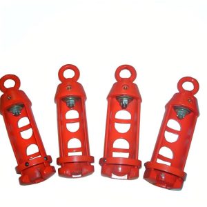
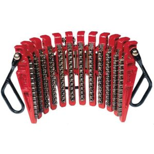
Description
Pneumatic Spider for Oilfield Workover, Completion & Well Servicing
During tubing running and pulling, rig crews need to hold the pipe string securely at the well center while the hoisting system handles each joint. SGPE Pneumatic Spider performs this task through a mechanical gripping assembly and an air-operated slip mechanism.
Compressed air raises and lowers the slips. As the crew transfers the string load, the tapered bowl and gripping components provide mechanical support. This arrangement reduces the repeated physical effort involved in handling conventional manual slips.
SGPE supplies C, CHD, HD, E and QQP Pneumatic Spiders for production tubing, compatible drill pipe and selected casing. The published range includes rated capacities from 60 to 175 US short tons and selected tubular outside diameters from 1.315 to 7-5/8 in (33.4–193.7 mm).
These oilfield tubular-handling tools support tubing running, tubing pulling, well completion, recompletion, workover and selected drilling operations. Depending on the configuration, contractors use them on land drilling rigs, offshore platforms, jack-up rigs, workover rigs, pulling units and well-service equipment.
The correct spider depends on more than pipe diameter. Suspended string weight, slip-body geometry, rig-floor space and available compressed air all affect equipment selection.
SGPE supports complete equipment supply, matched slip assemblies, replacement gripping inserts, spare-parts enquiries and dimensional cross-reference for existing rigs.
Email: info@sgpe.com
Tel / WhatsApp: +86 186-1599-5239
Technical Specifications and Product Overview
The SGPE range includes several load classes and gripping arrangements for different oilfield applications. Each model requires a suitable slip assembly and compatible installation.
General Technical Parameters
| Parameter | Specification |
|---|---|
| Product Name | Pneumatic Spider |
| Equipment Category | Oilfield Tubular Handling Equipment |
| Alternative Names | Pneumatic Tubing Spider, Air Operated Spider, Pneumatic Pipe Spider |
| Available Models | C, CHD, HD, E, QQP/60, QQP/75 and QQP/100 |
| Rated Capacities | 60, 75, 80, 100, 120, 125 and 175 US Short Tons |
| Combined Tubular OD Range | Selected Sizes from 1.315 to 7-5/8 in |
| Metric OD Coverage | Approximately 33.4–193.7 mm |
| Applicable Tubulars | Production Tubing, Compatible Drill Pipe and Selected Casing |
| Operating Medium | Compressed Air |
| Slip Actuation | Pneumatic Operating Mechanism |
| Load-Support System | Mechanical Slips and Tapered Bowl |
| Gripping Components | Slip Bodies, Slip Segments and Gripping Inserts |
| Structural Material | Selected Alloy Steel, According to Model |
| Installation | Compatible Rig-Floor or Rotary-Table Arrangement |
| Applicable Standard | API Spec 7K Requirements |
| Main Applications | Tubing Running, Pulling, Completion, Workover and Drilling Support |
| Replacement Parts | Slip Assemblies, Gripping Inserts and Selected Pneumatic Components |
The combined diameter range describes the complete product family. It does not mean that one spider or one set of inserts can grip every pipe size between these limits.
Each configuration requires the correct gripping assembly, rated capacity and installation arrangement.
Available Pneumatic Spider Models and Rated Capacities
SGPE offers seven published model configurations for different pipe sizes and suspended loads.
C, CHD, HD, E and QQP Model Comparison
| Model | Selected Tubular OD Range | Metric OD Range | Rated Capacity | Typical Application |
|---|---|---|---|---|
| C | 1.315–5-1/2 in | 33.4–139.7 mm | 80 short tons | Tubing Running, Pulling and Workover |
| CHD | 1.315–5-1/2 in | 33.4–139.7 mm | 120 short tons | Higher-Load Tubing Handling |
| HD | 1.315–5-1/2 in | 33.4–139.7 mm | 125 short tons | Heavy-Duty Tubular Support |
| E | 2-3/8–7-5/8 in | 60.3–193.7 mm | 175 short tons | Larger Tubulars and Selected Casing |
| QQP/60 | 2-3/8–3-1/2 in | 60.3–88.9 mm | 60 short tons | Routine Tubing and Well Servicing |
| QQP/75 | 2-3/8–3-1/2 in | 60.3–88.9 mm | 75 short tons | Tubing Handling and Workover |
| QQP/100 | 2-3/8–5 in | 60.3–127.0 mm | 100 short tons | Tubing and Compatible Drill Pipe |
All ratings refer to US short tons, not metric tonnes. Actual operating limits depend on the selected equipment, gripping assembly and approved handling procedure.
Need help choosing a model? Send SGPE your tubular OD, maximum suspended load, rig type and quantity. We can review suitable configurations and prepare a project-specific quotation.
C Pneumatic Spider – 80 Ton
The C Pneumatic Spider offers an 80 US short ton rated capacity for production tubing handling, well completion and routine oilfield workover.
Its available gripping configurations accommodate selected tubular outside diameters from 1.315 to 5-1/2 in. The range includes different slip-body arrangements for smaller tubing sizes and integral slip configurations for larger diameters.
The C model is a practical choice for workover rigs and pulling units where the expected suspended load falls within its approved capacity. Operators handling several tubing sizes can specify the corresponding slip assemblies for each pipe diameter.
For existing C-series installations, SGPE can review the original equipment dimensions and gripping requirements to assess suitable replacement options.
CHD Pneumatic Spider – 120 Ton
The CHD Pneumatic Spider provides a 120 US short ton rated capacity for heavier tubing strings and higher-load workover operations.
Although its published tubular diameter range matches the C series, CHD offers a higher load rating. This makes it an option for tubing programs that require greater supporting capacity without moving to a larger nominal pipe-size range.
CHD is relevant to production tubing replacement, completion-string recovery and selected drill pipe handling where the actual suspended load and gripping arrangement meet the equipment’s operating requirements.
When comparing C and CHD models, buyers should consider both rated capacity and the approved slip-body configuration, rather than selecting equipment by pipe diameter alone.
HD Pneumatic Spider – 125 Ton
The HD Pneumatic Spider offers a 125 US short ton rated capacity for heavy-duty tubular handling during oilfield workover and selected drilling operations.
Like CHD, the HD series accommodates selected pipe diameters from 1.315 to 5-1/2 in. However, the two models should not be treated as interchangeable simply because their published gripping ranges overlap.
The difference between their rated capacities is relatively small. Therefore, buyers should also compare the equipment’s structural design, bowl geometry, pneumatic operating arrangement and mounting interface.
For projects replacing an existing HD spider, original drawings and nameplate details can help identify the correct configuration and avoid unnecessary installation modifications.
E Pneumatic Spider – 175 Ton
The E Pneumatic Spider provides a 175 US short ton rated capacity, making it the highest-capacity model in SGPE’s published C, CHD, HD and E range.
It accommodates selected tubular outside diameters from 2-3/8 to 7-5/8 in through different slip-body configurations. These include larger gripping assemblies and a dedicated 7-5/8 in integral slip arrangement.
The E series is particularly relevant to heavier tubing strings, larger-diameter tubulars and selected casing-support operations that require greater rated capacity or gripping coverage.
Because the model uses different slip-body sizes across its operating range, the correct assembly must match the actual tubular diameter and approved load requirements. Buyers should also confirm the installation arrangement, especially when replacing equipment on an existing drilling or workover rig.
QQP Pneumatic Spider – 60, 75 and 100 Ton
The QQP Pneumatic Spider series offers three rated-load options for production tubing, compatible drill pipe and oilfield workover applications.
QQP/60 accommodates selected tubular diameters from 2-3/8 to 3-1/2 in with a 60 US short ton rated capacity. It suits routine tubing programs on compatible workover rigs, pulling units and well-service equipment.
QQP/75 covers the same published diameter range but increases the rated capacity to 75 US short tons. This provides an alternative when a tubing program requires a higher load rating without extending the nominal pipe-size range.
QQP/100 offers a 100 US short ton rated capacity and accommodates selected pipe diameters from 2-3/8 to 5 in. Its broader gripping range makes it relevant to workover projects involving larger tubing sizes or compatible drill pipe.
The three models allow buyers to compare load requirements and tubular diameter coverage within the QQP family. However, the selected gripping inserts and slip assemblies must still match the actual pipe size.
For QQP-specific technical specifications and model selection, visit SGPE QQP Pneumatic Spider.
Slip Body Sizes and Gripping Insert Specifications
The gripping assembly determines which tubular diameters a pneumatic spider can support.
A suitable configuration includes the correct slip body, gripping segments, inserts and tapered bowl. Different pipe sizes may require separate insert sets or complete slip assemblies.
C, CHD and HD Slip Body Specifications
| Applicable Tubular OD | Metric OD | Slip Body | Applicable Models |
|---|---|---|---|
| 1.315–3-1/2 in | 33.4–88.9 mm | 3-1/2 in | C / CHD / HD |
| 3-1/2–4-1/2 in | 88.9–114.3 mm | 4-1/2 in | C / CHD / HD |
| 4-3/4 in | 120.7 mm | 4-3/4 in Integral | C / CHD / HD |
| 5 in | 127.0 mm | 5 in Integral | C / CHD / HD |
| 5-1/2 in | 139.7 mm | 5-1/2 in Integral | C / CHD / HD |
These models share the listed nominal slip-body configurations but have different rated capacities.
The slip-body designation identifies a gripping assembly family. It does not mean that one insert set can handle every diameter within that family.
E Pneumatic Spider Slip Body Specifications
| Applicable Tubular OD | Metric OD | Slip Body | Rated Capacity |
|---|---|---|---|
| 2-3/8–3-1/2 in | 60.3–88.9 mm | 3-1/2 in | 175 short tons |
| 4–5-1/2 in | 101.6–139.7 mm | 5-1/2 in | 175 short tons |
| 5-1/2–7 in | 139.7–177.8 mm | 7 in | 175 short tons |
| 7-5/8 in | 193.7 mm | 7-5/8 in Integral | 175 short tons |
The E series uses different gripping assemblies for smaller and larger tubulars.
Slip-body selection at range boundaries: Published ranges meet or overlap at certain nominal diameters, including 3-1/2 in for C/CHD/HD and 5-1/2 in for E. Customers should confirm the manufacturer-approved slip body and gripping inserts for these sizes. Different assemblies are not automatically interchangeable.
QQP Slip Assemblies and Gripping Range
QQP/60 and QQP/75 accommodate selected 2-3/8 to 3-1/2 in tubulars, while QQP/100 extends the published range to 5 in.
Replacement slip sets must match the actual pipe OD and spider model. When ordering parts for existing equipment, include the slip-body dimensions, gripping-insert profile and any available part numbers.
Common Tubing Sizes and Specialty Tubulars
Typical production tubing outside diameters include 2-3/8, 2-7/8 and 3-1/2 in. Some projects also require 4, 4-1/2, 5 or 5-1/2 in gripping arrangements.
The correct insert profile matters as much as the nominal size. A spider may cover a broad published diameter range, but each pipe size still requires a suitable gripping assembly.
Production tubing may use external-upset-end (EUE), non-upset-end (NUE) or premium connections. Buyers should confirm the pipe-body OD and provide enough clearance for couplings, upsets and other connection features.
Material compatibility is equally important. Standard hardened inserts may leave marks on conventional steel tubing. Chrome tubing, corrosion-resistant alloy (CRA) tubulars, coated pipe and premium completion strings may require a different gripping arrangement.
For these applications, provide the pipe grade, wall thickness, surface finish, permitted gripping location and acceptable marking requirements.
SGPE can assess available slip configurations using the supplied tubular information.
How Does a Pneumatic Spider Work?
A pneumatic spider uses compressed air to move the slips and a mechanical gripping assembly to support the pipe string.
Pneumatic Slip Actuation
The operator activates the air-control system. A pneumatic actuator moves the operating linkage to raise or lower the slips.
This reduces manual movement during repeated pipe-handling cycles.
Tubular Engagement and Load Transfer
The slips move into position around the designated gripping area.
As the crew transfers the string load, the inserts contact the tubular and the tapered bowl develops mechanical gripping force.
The spider body and matched gripping components support the load within the equipment’s approved operating limits.
Meanwhile, the elevator connects to the rig’s hoisting system and handles the lifting or lowering movement.
Controlled Slip Release
Before releasing the spider, the crew must transfer the required string load to the receiving equipment according to the approved operating procedure.
The operator then activates pneumatic control to disengage the slips, allowing the elevator to continue moving the string.
Crews repeat this sequence during tubing running, tubing pulling and other suitable tubular-handling operations.
Important: Compressed air operates the slips. It does not independently carry the suspended pipe-string load.
Air Supply and Rig-Floor Installation Requirements
A pneumatic tubing spider must match the rig’s compressed-air supply, mounting arrangement and available operating space.
Working pressure, air consumption, actuator design, overall dimensions and equipment weight depend on the selected model.
Pneumatic and Mechanical Selection Parameters
| Parameter | Requirement |
|---|---|
| Operating Medium | Compressed Air |
| Slip Actuation | Model-Specific Pneumatic Mechanism |
| Working Air Pressure | Confirm from Approved Model Datasheet |
| Maximum Permitted Pressure | Follow Manufacturer’s Operating Limits |
| Air Consumption | Confirm at Required Operating Pressure |
| Control Valve and Air Connections | Match Selected Pneumatic System |
| Slip Body and Bowl Geometry | Match Approved Gripping Assembly |
| Mounting Dimensions | Confirm from General Arrangement Drawing |
| Overall Dimensions and Net Weight | Confirm for Complete Configuration |
| Offshore Protection | Review Project-Specific Requirements |
| Inspection and Testing | Define in Purchasing Specification |
The published model tables do not establish universal pressure, airflow or dimensional values for every configuration.
Before installation, customers should obtain the technical datasheet and general arrangement drawing for the exact equipment. Specifications from another manufacturer’s similarly named spider should not replace these documents.
Key Features and Operating Benefits
Reduced Manual Slip Handling
Pneumatic actuation reduces the need to repeatedly lift and reposition heavy slips by hand.
This is particularly useful on workover rigs and service units that handle numerous tubing joints during a single operation.
Multiple Load and Gripping Configurations
SGPE offers several rated-load classes for different production tubing and compatible drill pipe programs.
Matched slip bodies and inserts allow customers to specify the gripping components needed for their actual tubular sizes.
Serviceable Components
Major load-bearing components use selected alloy-steel construction according to the equipment design.
Operators can inspect and replace approved gripping inserts, retaining hardware and selected pneumatic parts during planned maintenance.
Replacement Equipment Support
Existing workover rigs may use different mounting dimensions, pneumatic controls and structural arrangements.
SGPE can review drawings, nameplate information and gripping requirements when assessing replacement equipment.
Pneumatic Spider Applications in Oil and Gas Operations
Pneumatic spiders support tubular handling during drilling, well completion, workover and production-well maintenance.
1. Production Tubing Running and Pulling
Tubing running and tubing pulling are primary applications for an air-operated tubing spider.
During tubing running, crews lower successive joints into the well while the spider holds the remaining string at the designated well-center position.
During tubing pulling, the string moves upward for joint removal, inspection or replacement. The spider provides support during the approved connection-handling sequence.
These operations are common on workover rigs, pulling units, completion rigs and well-service equipment.
2. Oil Well Workover and Well Servicing
Workover contractors use compatible pneumatic spiders during tubing replacement, leak repair, remedial workover and completion-string recovery.
The equipment provides stationary tubular support while the rig’s hoisting system handles pipe movement.
For workover rig installations, customers should consider suspended string load, pipe OD, available compressed air and mounting dimensions.
3. Well Completion and Recompletion
During oil and gas well completion, crews install production tubing as part of the planned completion program.
Recompletion may require removal of an existing tubing string, replacement of damaged components or installation of a new completion arrangement.
A suitable pneumatic spider helps manage repeated tubular gripping and release during these operations.
4. Artificial Lift, Rod-Pump and ESP Workover
Artificial-lift maintenance often involves production tubing retrieval to access or replace downhole equipment.
In rod-pumped wells, crews may remove the sucker rod string before pulling the tubing. A pneumatic spider supports the tubing-handling stage; separate rod-handling equipment manages the sucker rods.
Electric submersible pump (ESP) workover can also require tubing retrieval or installation.
However, ESP power cables, cable protectors and clamps may restrict the available gripping area. The spider must not grip or damage the power cable.
For ESP projects, buyers should provide the tubing OD, cable position, completion arrangement and maximum suspended load.
5. Gas Well Servicing and Well Intervention
Gas well workover may involve retrieving tubing for completion repair, inspection or replacement.
A pneumatic spider can support jointed tubing during approved running and pulling procedures.
The equipment provides mechanical pipe support only. It does not control well pressure or replace pressure-control equipment.
Operators must use suitable well-control systems for the actual well conditions.
6. Drill Pipe and Selected Casing Handling
Selected configurations can support compatible drill pipe during approved drilling-related and workover operations.
These applications may involve pipe-string holding, selected tripping support and tubular handling during connection work.
Certain models can also support selected casing diameters during remedial casing operations or recovery.
Drill pipe and casing compatibility requires confirmation of pipe OD, string load, gripping location and slip geometry. Larger casing programs may need dedicated casing spiders or elevator-spider systems.
A standard pneumatic spider does not apply connection makeup or breakout torque. It also cannot replace every conventional rotary-table slip arrangement.
7. Offshore Drilling, Jack-Up Rigs and Remote Oilfields
Suitable pneumatic spiders can support selected tubular-handling operations on offshore platforms, jack-up rigs and offshore workover units.
Offshore equipment selection should account for mounting dimensions, corrosion protection, operating controls, inspection requirements and spare-parts availability.
Remote oilfields and truck-mounted workover rigs may also face limited installation space or slower access to replacement components.
Accurate installation drawings and an appropriate spare-parts package help contractors prepare for these conditions.
Pneumatic Spider vs. Manual Spider, Hydraulic Spider and Tubing Elevator
Different tubular-handling tools serve different functions on the rig floor.
| Equipment | Operating Method | Main Function | Typical Application |
|---|---|---|---|
| Pneumatic Spider | Compressed-Air Actuation | Supports Tubular String at Rig Floor | Tubing Running, Pulling and Workover |
| Manual Spider | Manual Slip Operation | Stationary Tubular Support | Conventional Pipe Handling |
| Hydraulic Spider | Hydraulic Actuation | Mechanized Tubular Holding | Compatible Hydraulic Rig Systems |
| Tubing Elevator | Hoisting Equipment | Lifts and Lowers Tubing | Completion and Workover |
| Slip Elevator Spider | Model-Specific Combined Design | Approved Lifting and Gripping | Specialized Tubular Running |
A manual spider requires hand operation of its gripping mechanism. Pneumatic and hydraulic spiders use compressed air and hydraulic power respectively.
A Tubing Elevator has a different role. It connects to the hoisting system and lifts or lowers the pipe, while a standard spider holds the string at the rig floor.
The two tools often work together, but they are not interchangeable.
For related equipment, see SGPE Tubing Elevators and SGPE SE500 Slip Elevator Spider.
How to Select the Right Pneumatic Spider
Selecting suitable equipment requires a review of the tubular program, suspended load and rig-floor arrangement.
Tubular OD and Maximum Suspended Load
Start with the actual pipe-body OD, tubular type, wall thickness, material grade and designated gripping location.
Then calculate the maximum suspended string load according to the operator’s engineering procedures.
The selected model must satisfy both the pipe-size and load requirements.
Slip Assemblies and Installation
The spider must use a compatible tapered bowl, slip body and gripping-insert arrangement.
For projects involving several tubing sizes, identify each required insert set before ordering.
Buyers should also confirm the mounting footprint, supporting structure, available clearance and rotary-table interface where applicable.
Compressed Air and Documentation
Check the rig’s air pressure, airflow and connection requirements against the selected equipment’s datasheet.
For replacement equipment, provide the original model, nameplate, mounting dimensions and photographs.
Technical procurement may also require general arrangement drawings, inspection records, operating manuals and spare-parts details.
Pneumatic Spider Spare Parts and Replacement Components
SGPE supports enquiries for complete spiders, matched slip assemblies and selected replacement components.
Common requirements include pneumatic spider slip inserts, spider dies, slip bodies, operating links, pneumatic cylinders, control valves and service parts.
Common Pneumatic Spider Components
| Component | Main Function | Selection Information |
|---|---|---|
| Spider Body | Structural Load Support | Model and Rated Capacity |
| Tapered Bowl | Mechanical Gripping Interface | Bowl Geometry |
| Slip Bodies and Segments | Support Gripping Components | Model and Tubular OD |
| Slip Inserts / Spider Dies | Contact and Grip Tubular Surface | OD and Insert Profile |
| Pneumatic Cylinder | Moves Slip Assembly | Actuator Model |
| Operating Links and Pins | Transfer Actuator Movement | Part Number and Dimensions |
| Air Control Valve | Controls Pneumatic Actuation | Valve and Control Arrangement |
| Hoses and Fittings | Connect Air Supply | Pressure and Connection Size |
| Bushings and Retaining Hardware | Support and Secure Components | Approved Assembly |
| Seals and Service Parts | Support Pneumatic Maintenance | Cylinder and Seal Dimensions |
Replacement Slip Inserts and Gripping Dies
Gripping inserts wear as they repeatedly contact tubular surfaces. Damaged teeth or incorrect contact geometry can affect gripping performance.
Operators should inspect these components and replace worn inserts according to the manufacturer’s maintenance criteria.
For replacement enquiries, provide the spider model, actual tubular OD, insert dimensions, tooth profile, retaining arrangement and required quantity.
SGPE also supports related Tong Dies and Slip Inserts enquiries.
Existing Spider Replacement and Model Cross-Reference
Older rig-floor equipment may use model designations such as Type B, Type G, Type F, T-60, QP30 or alternative QQP load classes.
These names can help identify replacement requirements, but they do not establish SGPE stock availability or automatic compatibility.
For a dimensional cross-reference, provide the original manufacturer, complete model number, rated capacity, mounting dimensions and available drawings.
SGPE can assess possible replacement configurations using the actual equipment details. Similar model names do not guarantee interchangeable slip bodies or spare parts.
Inspection, Maintenance and Safe Operation
Pneumatic spiders support suspended tubular loads and require regular inspection.
Before use, trained personnel should check the body, bowl, slips, gripping inserts, retaining hardware and pneumatic components for cracks, deformation, worn teeth, air leaks or abnormal movement.
During operation, crews must follow the approved load-transfer procedure between the spider and elevator. The supporting slips must not be released before the receiving equipment takes the required load.
After use, operators should clean the equipment and complete the necessary lubrication, inspection and corrosion-protection work.
Replace worn parts only with components approved for the equipment configuration.
Safety Reminder: Never exceed the spider’s approved rated capacity. Follow the manufacturer’s instructions, the rig’s lifting procedures and applicable well-control requirements.
API Spec 7K Requirements and Quality Documentation
SGPE offers pneumatic spider configurations designed around applicable API Spec 7K – Drilling and Well Servicing Equipment requirements.
The standard covers relevant drilling and well-servicing equipment, including spiders that do not function as hoisting elevators.
For each project, buyers should confirm the applicable standard edition, equipment classification and required inspection scope.
Depending on the agreed supply package, documentation may include general arrangement drawings, material specifications, rated-capacity identification, slip-body details, dimensional inspection records and factory testing information.
Some customers also require operating manuals, load-test documentation, certificates of conformity or third-party inspection.
These requirements should be agreed before order confirmation.
API Spec 7K conformity and API Monogram licensing are separate matters. A statement about applicable API requirements does not automatically establish API Monogram authorization. Buyers requiring specific certification or licensing evidence should verify it for the exact equipment and manufacturing facility.
OEM Pneumatic Spider and Replacement Equipment Support
SGPE supports drilling contractors, workover companies, well-service providers and oilfield equipment distributors with new equipment and replacement enquiries.
For new installations, customers can compare the C, CHD, HD, E and QQP series according to tubular size, rated capacity and available rig utilities.
For existing rigs, SGPE can review mounting dimensions, gripping assemblies, pneumatic controls and original equipment drawings.
Buyers may also request matched slip sets, replacement inserts, technical documentation, OEM configuration reviews and international supply quotations.
Available modifications depend on engineering feasibility and the approved equipment design.
Pneumatic Spider Supplier, Pricing and RFQ Support
SGPE supplies pneumatic spiders, matched slip assemblies and selected replacement parts for oilfield drilling, completion and workover projects.
For buyers comparing pneumatic spider manufacturers and suppliers, the most important considerations are rated capacity, pipe-size compatibility, installation requirements, technical documentation and spare-parts support.
Pricing depends on the selected model, gripping configuration, pneumatic accessories and order quantity. Additional slip sets, OEM requirements, inspection documents and delivery arrangements can also affect the final quotation.
For an initial price enquiry, send SGPE the actual tubular OD, maximum suspended load, preferred model, quantity and destination.
Pneumatic Spider RFQ Checklist
| Required Information | Details to Provide |
|---|---|
| Preferred Model | C / CHD / HD / E / QQP or Existing Equipment |
| Tubular Type and OD | Production Tubing / Drill Pipe / Casing; Actual OD |
| Maximum Suspended Load | Required Load and Units |
| Gripping Configuration | Slip Bodies, Inserts and Number of Sets |
| Rig and Installation | Workover / Drilling / Offshore; Mounting Dimensions |
| Pneumatic Supply | Available Pressure, Airflow and Connections |
| Quantity and Spare Parts | Complete Equipment and Replacement Sets |
| Documentation | Drawings, Inspection, Testing and Certificates |
| Delivery Destination | Country or Destination Port |
For replacement equipment, include the original nameplate and photographs.
These details help SGPE review the suitable configuration and prepare a technical and commercial proposal.
Frequently Asked Questions About Pneumatic Spiders
1. What is a Pneumatic Spider, and how does it work?
A Pneumatic Spider is an air-operated oilfield tubular-handling tool that grips and supports pipe strings at the well center during drilling, well completion and workover operations.
The pneumatic system raises and lowers the gripping slips, while the tapered bowl and mechanical gripping components support the suspended tubular load. Unlike manual slips, pneumatic actuation reduces the physical effort involved in repeated gripping and releasing.
During tubing running and pulling, the spider works with a tubing elevator to hold the string while crews position, connect or remove individual joints. This makes it particularly useful on workover rigs, pulling units and well-service equipment that handle production tubing throughout the day.
2. Is a Pneumatic Spider the same as a Pneumatic Tubing Spider?
The terms Pneumatic Spider, Pneumatic Tubing Spider and Air-Operated Tubing Spider often describe the same general type of rig-floor tubular-holding equipment.
Pneumatic Tubing Spider usually emphasizes production tubing applications, including tubing running, tubing pulling, well completion and oilfield workover. The broader term Pneumatic Spider may also include configurations for compatible drill pipe and selected casing.
However, similar product names do not guarantee identical specifications or interchangeable parts. Each model has its own rated capacity, gripping range and slip-body arrangement.
Before selecting equipment, buyers should confirm the actual pipe outside diameter, tubular type, suspended load and approved gripping assembly.
3. Which SGPE Pneumatic Spider models and rated capacities are available?
SGPE offers C, CHD, HD, E and QQP Pneumatic Spiders for different tubular-handling requirements.
The C model provides an 80 US short ton rated capacity, while CHD and HD offer 120 and 125 US short tons respectively. The E model provides 175 US short tons for heavier strings and larger-diameter tubulars.
The QQP series includes QQP/60, QQP/75 and QQP/100, with corresponding rated capacities of 60, 75 and 100 US short tons.
These models serve different tubing, workover and selected drill pipe handling applications. For example, a routine production tubing program may require a different configuration from a higher-load completion-string recovery operation.
Buyers should compare both rated capacity and pipe-size compatibility before choosing a model.
4. What tubing and drill pipe sizes can SGPE Pneumatic Spiders handle?
SGPE’s combined pneumatic spider range accommodates selected tubular outside diameters from 1.315 to 7-5/8 in (33.4–193.7 mm), depending on the model and slip assembly.
The C, CHD and HD series cover selected sizes up to 5-1/2 in, while the E series extends to 7-5/8 in. QQP/60 and QQP/75 accommodate selected 2-3/8 to 3-1/2 in tubulars, and QQP/100 extends to 5 in.
Common tubing sizes include 2-3/8, 2-7/8 and 3-1/2 in. However, each diameter requires suitable gripping inserts and a compatible slip-body configuration.
For EUE, NUE or premium tubing connections, buyers should also consider coupling clearance and the permitted gripping location.
5. Can a Pneumatic Spider handle drill pipe, casing or CRA tubing?
Selected pneumatic spider configurations can support compatible drill pipe and casing in addition to conventional production tubing, provided the pipe dimensions, suspended load and gripping arrangement meet the equipment’s approved requirements.
Drill pipe handling may be relevant during selected drilling-support and workover operations. Certain larger-capacity models may also suit approved casing-support applications, although specialized casing-running equipment may be necessary for heavier strings.
Tubular material requires particular attention. Conventional hardened slip inserts can mark pipe surfaces, so chrome tubing, corrosion-resistant alloy (CRA) tubulars, coated pipe and premium completion strings may need a different gripping arrangement.
During ESP workover, crews must also protect the power cable and cable protectors from slip contact. A pneumatic spider supports compatible tubulars; it does not replace dedicated sucker rod handling equipment.
6. Which Pneumatic Spider is suitable for a workover rig?
The best Pneumatic Spider for a Workover Rig depends on the tubing outside diameter, maximum suspended string load, available compressed-air supply and rig-floor installation.
C and QQP models offer options for routine production tubing running and pulling on compatible workover rigs, pulling units and well-service equipment. For heavier tubing strings or higher-load operations, contractors may consider CHD, HD or E configurations.
Truck-mounted workover rigs and offshore well-servicing units may have additional restrictions involving mounting dimensions, operating space and equipment interfaces.
For an existing rig, SGPE can review the original spider model, nameplate information and installation drawings to assess possible replacement options. The selected equipment must use the correct slip assembly and remain within its approved operating limits.
7. What working air pressure does a Pneumatic Spider require?
A Pneumatic Spider uses compressed air to operate its gripping slips, but the required working pressure and air consumption depend on the specific model, actuator and control system.
Before installation, operators should check the manufacturer’s approved operating-pressure range, maximum permitted pressure, airflow requirements and pneumatic connection sizes.
These details are especially important when installing an air-operated spider on an existing workover rig, offshore platform or service unit with a shared compressed-air supply.
The pneumatic system must provide suitable actuation throughout the operating cycle. However, compressed air does not independently carry the suspended tubular load; the mechanical gripping assembly provides that support.
SGPE recommends confirming model-specific pneumatic specifications rather than applying pressure settings from another manufacturer’s equipment.
8. What is the difference between Pneumatic, Manual and Hydraulic Spiders?
The main difference between Pneumatic, Manual and Hydraulic Spiders is how their gripping slips move.
A Manual Spider requires operators to position or release the slips by hand. A Pneumatic Spider uses compressed air, while a Hydraulic Spider uses hydraulic power to operate its mechanism.
Pneumatic actuation reduces repetitive manual slip handling and can be useful during frequent tubing running and pulling operations. Hydraulic models may suit rigs with compatible hydraulic systems, while manual spiders remain an option for appropriate conventional handling procedures.
The choice depends on the rig’s available utilities, tubular-handling frequency, suspended load and installation requirements.
Regardless of the operating method, each spider must use a suitable gripping assembly and remain within its approved rated capacity.
9. Can a Pneumatic Spider replace a Tubing Elevator?
No. A standard Pneumatic Spider and a Tubing Elevator perform different functions during oilfield tubular handling.
The spider supports the pipe string at the rig floor, while the tubing elevator connects to the hoisting system and lifts or lowers the tubulars.
During production tubing running or pulling, crews use the two tools together to transfer the string load between the stationary spider and the elevator. The crew must complete the required load transfer before releasing the supporting slips.
This arrangement is common during well completion, oilfield workover and tubing replacement.
Some specialized Slip Elevator Spider designs combine approved lifting and gripping functions. However, operators must not use a conventional pneumatic spider as a hoisting elevator without specific manufacturer approval.
10. What Pneumatic Spider spare parts and replacement components does SGPE offer?
SGPE supports enquiries for Pneumatic Spider Spare Parts, including compatible slip bodies, gripping inserts, spider dies, matched slip assemblies and selected pneumatic operating components.
Replacement requirements may also involve pneumatic cylinders, control valves, operating links, pins, bushings, hoses, fittings, seals and retaining hardware.
During repeated tubing running and pulling operations, gripping inserts can wear through regular contact with the pipe surface. Timely inspection and replacement of worn components help maintain the equipment’s approved gripping condition.
For accurate spare-parts identification, customers should provide the original manufacturer, spider model, tubular OD, component dimensions and available part numbers or photographs.
SGPE can review these details to assess suitable replacement components for existing drilling, completion and workover equipment.
11. Does SGPE supply API Spec 7K Pneumatic Spiders with inspection documentation?
SGPE offers pneumatic spider configurations designed around applicable API Spec 7K – Drilling and Well Servicing Equipment requirements.
For international drilling, completion and workover projects, buyers should confirm the applicable standard edition, equipment classification and documentation requirements for the selected model.
Depending on the agreed supply scope, customers may request technical drawings, material information, dimensional inspection records, factory testing documentation, operating manuals or third-party inspection arrangements.
However, API Spec 7K conformity does not automatically establish API Monogram licensing. Any required API Monogram authorization, certificate or licensing evidence must be verified for the specific equipment and manufacturing facility.
Buyers should communicate their inspection and certification requirements before order confirmation so that SGPE can review the available documentation.
12. What affects Pneumatic Spider price, and how can I request a quotation?
The Pneumatic Spider price depends on the selected model, rated capacity, tubular gripping range, slip assemblies, pneumatic accessories and order quantity.
Additional gripping inserts, replacement parts, OEM requirements, inspection documentation and delivery arrangements may also affect the final quotation.
For new workover rigs, completion projects or replacement equipment, customers should provide the tubular type and outside diameter, maximum suspended load, preferred model, quantity and delivery destination. Information about the rig’s mounting arrangement and compressed-air supply can also help confirm equipment compatibility.
If the enquiry concerns an existing spider, the original nameplate, model number and dimensional drawings will support the replacement review.
SGPE will assess your technical requirements, identify a suitable Pneumatic Spider configuration and provide a project-specific quotation based on your equipment specifications, order quantity and delivery needs.
Request a Pneumatic Spider Quote from SGPE
SGPE supplies C, CHD, HD, E and QQP Pneumatic Spiders for tubing running, tubing pulling, well completion, oilfield workover and selected drilling operations. We also offer compatible slip assemblies, gripping inserts and replacement parts.
Whether you are equipping a new drilling or workover rig, replacing an existing spider or sourcing spare parts, SGPE can help you identify a suitable configuration based on your tubular sizes, suspended loads and operating requirements.
To request a quotation, please provide your tubular type and outside diameter (OD), maximum suspended load, preferred model, quantity and delivery destination. Details of your rig type, mounting arrangement, required slip assemblies and inspection documentation will also help us prepare an accurate offer.
For replacement equipment, include the original model number, nameplate photographs and available dimensional drawings. This information helps us assess compatibility and identify suitable replacement options.
Email: info@sgpe.com
Tel / WhatsApp: +86 186-1599-5239