Description
Quintuplex Frac Pump for Shale Fracturing, Horizontal Wells and High-Pressure Well Stimulation
SGPE manufactures Quintuplex Frac Pump equipment for hydraulic fracturing, well stimulation and other high-pressure oilfield pressure-pumping operations. The SGPE Model 1000 uses a horizontal five-cylinder reciprocating plunger design to provide smoother fluid delivery, lower pulsation and stable discharge under demanding well-service conditions.
The Model 1000 Quintuplex Frac Plunger Pump provides up to 1,000 bhp (746 kW) of input power, a maximum connecting rod load of 100,000 lbf (445 kN) and a 6 in. (152.4 mm) stroke. Its compact direct plunger-to-crosshead arrangement helps reduce overall pump length and makes the unit easier to integrate into frac trailers, skid-mounted stimulation systems and OEM pressure-pumping packages.
SGPE offers 3 in. and 3.5 in. fluid-end configurations. The final configuration depends on treating pressure, pumping rate, available horsepower, fluid properties, proppant conditions, duty cycle and the mechanical interfaces of the complete pumping system.
As an oilfield Quintuplex Frac Pump manufacturer and supplier, SGPE supports complete pumps, OEM integration, custom frac pump projects, replacement equipment, fluid ends, selected power-end components and spare-parts requirements.
Typical customers include hydraulic fracturing contractors, pressure-pumping service companies, well-stimulation contractors, upstream oil and gas operators, completion companies, frac equipment manufacturers, EPC contractors and international oilfield procurement teams.
Email: info@sgpe.com
Tel / WhatsApp: +86 186-1599-5239
SGPE Model 1000 at a Glance
| Parameter | Model 1000 |
|---|---|
| Product | Quintuplex Frac Pump |
| Alternative Name | Quintuplex Frac Plunger Pump |
| Configuration | Horizontal Five-Cylinder Plunger Pump |
| Number of Cylinders / Plungers | 5 |
| Maximum Input Power | 1,000 bhp / 746 kW |
| Maximum Connecting Rod Load | 100,000 lbf / 445 kN |
| Stroke | 6 in. / 152.4 mm |
| Speed Ratio | 4.61:1 |
| Fluid End Options | 3 in. / 3.5 in. |
| Overall Dimensions | 74.6 × 50.8 × 31.11 in. |
| Metric Dimensions | 1,895 × 1,292 × 792 mm |
| Approximate Weight | 7,231 lb / 3,280 kg |
| Main Application | Hydraulic Fracturing |
| Other Applications | Well Stimulation, Acidizing, Selected Cementing, Well Service and High-Pressure Fluid Transfer |
| Installation | Trailer-Mounted, Skid-Mounted or OEM Integrated |
| Supply Scope | Complete Pump, Fluid End, Selected Power-End Components and Spare Parts |
Model 1000 Technical Specifications
Power End Specifications
| Parameter | Specification |
|---|---|
| Model | SGPE Model 1000 |
| Pump Type | Horizontal Quintuplex Plunger Pump |
| Number of Pumping Cylinders | 5 |
| Maximum Brake Horsepower | 1,000 bhp |
| Maximum Input Power | 746 kW |
| Maximum Connecting Rod Load | 100,000 lbf / 445 kN |
| Stroke Length | 6 in. / 152.4 mm |
| Speed Ratio | 4.61:1 |
| Length | 74.6 in. / 1,895 mm |
| Width | 50.8 in. / 1,292 mm |
| Height | 31.11 in. / 792 mm |
| Approximate Weight | 7,231 lb / 3,280 kg |
| Power-End Layout | Direct Plunger / Crosshead Arrangement |
| Typical Installation | Frac Trailer, Skid or OEM Pumping Package |
Fluid End and Pumping Configuration
| Parameter | Configuration / Selection Basis |
|---|---|
| Fluid End Size | 3 in. / 3.5 in. |
| Published Fluid-End Output | 40 sets/month |
| Fluid End Selection | Pressure, Flow and Operating Duty |
| Plunger Configuration | Selected for Required Operating Point |
| Working Pressure | Confirmed for Final Configuration |
| Pumping Rate | Confirmed According to Configuration and Pump Speed |
| Fluid-End Material | Selected According to Fluid and Project Requirements |
| Packing | Selected According to Fluid, Pressure and Temperature |
| Valves | Replaceable High-Pressure Wear Components |
| Valve Seats | Replaceable Wear Components |
| Suction Arrangement | Frac Blender or Low-Pressure Suction Manifold |
| Discharge Arrangement | High-Pressure Frac Manifold / Treating System |
| Connection Type | Project-Specific |
| Connection Size | Project-Specific |
| Slickwater Service | Subject to Technical Selection |
| Gel-Based Fracturing Fluid | Subject to Technical Selection |
| Proppant-Laden Fluid | Evaluate Particle Type, Size and Concentration |
| Acidizing Fluid | Material-Compatibility Review Required |
| Cementing Fluid | Fluid and Duty Review Required |
| Fluid Temperature | Project-Specific |
| Spare Parts Package | Available According to Service Duty |
Performance Note: The Model 1000 does not have one universal maximum working pressure or pumping rate for every configuration. Fluid-end selection, plunger configuration, pump speed, available horsepower, treatment fluid and complete pressure-system limits determine the final operating envelope. SGPE confirms the required pressure-flow duty during technical selection.
What Is a Quintuplex Frac Pump?
A Quintuplex Frac Pump is a positive-displacement reciprocating plunger pump with five pumping cylinders. Oilfield pressure-pumping companies use it to deliver treatment fluid into a well at the pressure and rate required for hydraulic fracturing and other stimulation operations.
The same equipment may also appear in project specifications or supplier searches as a five-cylinder frac pump, Quintuplex Plunger Pump, hydraulic fracturing pump, fracturing pump, fracking pump, oilfield frac pump, high-pressure plunger pump, well stimulation pump or well service pump.
These terms describe closely related pressure-pumping equipment. However, a suitable pump cannot be selected from a product name or horsepower rating alone. Treating pressure, pumping rate, available horsepower, treatment-fluid properties, proppant program and operating duty must be considered together.
A typical hydraulic-fracturing fluid path is:
Frac Blender → Low-Pressure Suction Manifold → Quintuplex Frac Pump → High-Pressure Frac Manifold → Treating Iron → Wellhead → Wellbore
The pump converts mechanical input from the prime mover into the high-pressure fluid output required by the treatment program.
How a Five-Cylinder Frac Pump Works
Mechanical power reaches the frac pump power end through the transmission. The crankshaft drives the connecting rods and crossheads, converting rotary motion into the reciprocating movement of five plungers.
During each suction stroke, the fluid end draws treatment fluid from the low-pressure supply system. On the discharge stroke, the plungers raise fluid pressure and move the treatment medium into the high-pressure treating system.
A conventional triplex pump uses three plungers, while a quintuplex design uses five. The additional pumping cylinders create more discharge events during each operating cycle.
Under comparable conditions, this arrangement can provide smoother fluid delivery and lower pulsation. More even discharge can also help reduce pressure fluctuation and vibration across frac manifolds, treating iron and connected high-pressure piping.
Key Features and Oilfield Benefits
| Feature | Model 1000 Design | Oilfield Benefit |
|---|---|---|
| Five-Cylinder Configuration | Five Reciprocating Plungers | Smoother Fluid Delivery |
| 1,000 bhp Input | 746 kW | Supports Demanding Pressure-Pumping Duty |
| 100,000 lbf Rod Load | 445 kN | Supports High Mechanical Loading |
| 6 in. Stroke | 152.4 mm | Compact Pump Geometry |
| Compact Power End | Direct Plunger / Crosshead Layout | Easier Trailer and Skid Integration |
| 3 in. / 3.5 in. Fluid Ends | Multiple Configurations | Supports Different Pressure-Flow Duties |
| Replaceable Wear Components | Valves, Seats, Packing and Plungers | Supports Field Maintenance |
| Flexible Installation | Trailer, Skid or OEM Integration | Fits Different Frac Pump Units |
| Component Supply | Pump, Fluid End and Selected Parts | Supports Fleet Maintenance |
| Replacement Support | Drawing and Interface Review | Supports Existing Equipment Upgrades |
Hydraulic Fracturing and Well Stimulation Applications
The Model 1000 can serve as a 1000 HP hydraulic fracturing pump when its selected fluid end and operating point match the treatment program.
Hydraulic fracturing requires sufficient surface pressure and fluid rate to initiate and extend fractures in an oil or gas reservoir. Depending on the treatment design, the pressure-pumping system may handle water, slickwater, linear gel, crosslinked gel, friction reducers, chemical additives, sand proppant or ceramic proppant.
Pumping conditions often change between pad, slurry and displacement stages. Therefore, engineers should not select a high-pressure frac pump from horsepower alone. Treating pressure, flow rate, hydraulic horsepower, fluid rheology, proppant concentration, suction conditions and duty cycle all influence the usable operating point.
| Application | Typical Oilfield Environment | Main Selection Focus |
|---|---|---|
| Shale Oil Fracturing | Horizontal Shale Oil Wells | Pressure, Rate and Proppant |
| Shale Gas Fracturing | Multi-Stage Shale Gas Completions | Flow, Pressure and Fleet Reliability |
| Tight Oil Stimulation | Low-Permeability Oil Reservoirs | Hydraulic Horsepower and Proppant |
| Tight Gas Stimulation | Low-Permeability Gas Reservoirs | Pressure-Flow Operating Point |
| Horizontal Well Fracturing | Long Lateral Completions | Multi-Stage Pumping Duty |
| Multi-Stage Fracturing | Repeated Completion Stages | Duty Cycle and Maintenance |
| Plug-and-Perf Completion | Staged Horizontal Well Completion | Pumping Schedule and Fleet Capacity |
| Refracturing | Existing Producing Wells | Current Well Conditions |
| Conventional Fracturing | Conventional Oil and Gas Reservoirs | Required Hydraulic Duty |
| Matrix Acidizing | Formation-Damage Removal | Acid Chemistry and Temperature |
| Selected Cementing | Well Construction and Remedial Work | Slurry Properties and Duty |
| Workover Pumping | Well Intervention | Fluid, Pressure and Equipment Layout |
| High-Pressure Fluid Transfer | Oilfield Well-Service Systems | Fluid Compatibility and Pressure Duty |
Shale, Horizontal Well and Multi-Stage Fracturing
Shale oil and shale gas development often combines horizontal drilling with multi-stage hydraulic fracturing. A long lateral may require many treatment stages, so the frac fleet must repeatedly deliver the required treating pressure and pumping rate while the fluid system and proppant schedule change throughout the job.
For a shale gas hydraulic fracturing pump or horizontal well fracturing pump application, engineers should review stage pressure, total required flow, available hydraulic horsepower, treatment fluid, proppant type, maximum concentration and expected pumping hours.
The Model 1000 can operate as part of a multi-pump frac spread when its approved operating range matches the completion design.
Multi-stage and plug-and-perf treatments also create repeated cyclic loading. Stable suction flow, accessible fluid-end components, reliable lubrication and suitable spare-parts planning become increasingly important as treatment stages accumulate.
Tight Reservoir Stimulation and Refracturing
Tight oil and tight gas reservoirs have low natural permeability. Operators use high-pressure stimulation to create additional conductive flow paths between the reservoir and the wellbore.
A well stimulation pump must provide the required pressure and rate without exceeding its hydraulic or mechanical limits. The actual pressure-flow operating point, available horsepower, treatment fluid, proppant program and package layout all influence selection.
Refracturing creates a similar challenge because an existing producing well may require different pumping conditions from its original completion.
For a refracturing project, buyers should provide current well conditions, required treating pressure, pumping rate, fluid program, available power and information about the existing pressure-pumping spread.
Slickwater, Gel and Proppant-Laden Service
A frac pump for slickwater fracturing may need to operate at relatively high surface flow rates. Stable suction performance therefore becomes particularly important.
Gel and crosslinked fluids may have greater viscosity than slickwater. Higher viscosity can influence fluid-end filling, suction pressure loss, valve response and mechanical loading.
Proppant introduces another challenge. Sand and ceramic particles help keep fractures open after treatment pressure falls, but these particles also increase abrasive wear inside the fluid end.
Fracturing Fluid and Service Matrix
| Fluid / Service | Typical Application | Main Engineering Focus |
|---|---|---|
| Slickwater | Shale Oil and Shale Gas Fracturing | Suction Stability and Pumping Rate |
| Linear Gel | Hydraulic Fracturing | Viscosity and Pump Filling |
| Crosslinked Gel | Proppant Transport | Rheology and Component Loading |
| Proppant Slurry | Hydraulic Fracturing | Abrasive Wear |
| Acidizing Fluid | Matrix Acidizing | Chemistry and Material Compatibility |
| Cement Slurry | Selected Cementing Operations | Density and Rheology |
| Well-Service Fluid | Workover and Intervention | Pressure, Rate and Compatibility |
For a proppant slurry frac pump application, provide the proppant type, particle size, maximum concentration, fluid rheology, treating pressure, pumping rate and expected pumping hours.
These details help engineers review fluid-end configuration and define a more realistic spare-parts plan for the expected service.
Acidizing, Cementing and Other Well-Service Duties
A suitable Model 1000 configuration can support selected acidizing and well-stimulation operations.
Acid chemistry may influence fluid-end materials, valves, valve seats, plungers, packing and seals. The acid type, concentration, additives, treatment temperature, pressure, rate and exposure time should therefore be included in the technical review.
Selected configurations can also support oilfield cementing, remedial pumping and workover service when the required hydraulic duty falls within the approved operating range.
Cement slurry and workover fluids behave differently from conventional fracturing fluids. Their density, rheology, required pressure, pumping rate and expected duty should be reviewed before the final configuration is confirmed.
Model 1000 Power End
The frac pump power end converts rotary mechanical input into reciprocating plunger movement. Major components typically include the crankshaft, connecting rods, crossheads, bearings and related drive parts.
The Model 1000 is rated for 1,000 bhp / 746 kW maximum input power, a maximum connecting rod load of 100,000 lbf / 445 kN, a 6 in. stroke and a 4.61:1 speed ratio.
The power end operates under repeated mechanical loading during high-pressure pumping service. Correct alignment, lubrication and load control therefore have a direct influence on long-term reliability.
For OEM packages, the prime mover, transmission, pump input conditions and equipment layout should be reviewed as one system rather than as separate components.
Model 1000 Fluid End
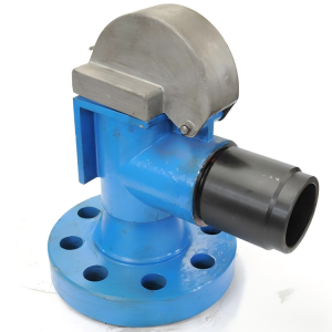
The frac pump fluid end handles the treatment medium directly at high pressure. Depending on the job, this may include slickwater, gel, chemical additives, proppant slurry, acidizing fluid or selected cementing fluids.
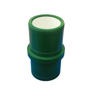
Key wear and service components include plungers, packing, valves, valve seats, seals and pressure-containing flow passages.
SGPE offers 3 in. and 3.5 in. fluid-end configurations for the Model 1000.
Fluid-End Selection Factors
| Selection Factor | Why It Matters |
|---|---|
| Treating Pressure | Defines Pressure Requirement |
| Pumping Rate | Defines Required Output |
| Available Horsepower | Limits Usable Operating Point |
| Pump Speed | Influences Output and Mechanical Duty |
| Fluid Density | Influences Hydraulic Loading |
| Fluid Viscosity | Influences Suction Performance |
| Fluid Rheology | Important for Gel and Slurry Service |
| Proppant Material | Influences Abrasive Wear |
| Proppant Size | Influences Flow-Path Wear |
| Proppant Concentration | Influences Wear Severity |
| Acid Chemistry | Influences Material Compatibility |
| Temperature | Influences Packing and Materials |
| Pumping Hours | Supports Spare-Parts Planning |
| Duty Cycle | Supports Maintenance Planning |
The correct 3 in. or 3.5 in. fluid end depends on the complete pressure-flow requirement rather than nominal size alone.
Treating pressure and pumping rate should be reviewed together with available horsepower, fluid properties, proppant information, operating temperature, duty cycle and equipment interfaces.
Pressure, Flow and Hydraulic Horsepower
Pressure alone does not define a frac pump requirement. Treating pressure, pumping rate and available horsepower are linked, while fluid-end configuration and pump speed influence the usable operating point.
| Selection Parameter | Engineering Role |
|---|---|
| Treating Pressure | Defines Discharge Pressure Requirement |
| Maximum Design Pressure | Defines System Design Basis |
| Pumping Rate | Defines Required Output |
| Hydraulic Horsepower | Links Pressure and Flow |
| Input Horsepower | Defines Available Mechanical Power |
| Pump Speed | Influences Pump Output |
| Fluid-End Configuration | Influences Operating Envelope |
| Fluid Properties | Influence Suction and Loading |
| Proppant | Influences Wear |
| Suction Conditions | Influence Pump Filling |
One well-stimulation program may require relatively high pressure at a moderate rate, while another may need greater flow at a lower pressure.
For this reason, the final pump should be selected around a defined pressure-flow operating point rather than a single maximum pressure or horsepower figure.
Triplex vs. Quintuplex Frac Pump
Triplex and quintuplex plunger pumps are both widely used in oilfield pressure-pumping equipment.
| Comparison | Quintuplex Frac Pump | Triplex Frac Pump |
|---|---|---|
| Number of Plungers | 5 | 3 |
| Discharge Events | More Frequent | Less Frequent |
| Flow Pulsation | Generally Lower Under Comparable Duty | Generally Higher |
| Discharge Smoothness | Smoother | More Pronounced Fluctuation |
| Vibration Potential | Lower Under Comparable Conditions | Higher Under Comparable Conditions |
| Package Integration | Suitable for Compact Pressure-Pumping Packages | Common in Conventional Well-Service Units |
| Typical Oilfield Use | Fracturing and Stimulation | Fracturing, Cementing and Well Service |
A five-cylinder pump is not automatically the better solution for every project.
Buyers should compare treating pressure, pumping rate, hydraulic horsepower, installation space, maintenance requirements, spare-parts availability, duty cycle and lifecycle cost before choosing between triplex and quintuplex equipment.
Trailer-Mounted, Skid-Mounted and OEM Integration
The compact Model 1000 supports different types of oilfield pressure-pumping equipment.
A trailer-mounted frac pump allows equipment manufacturers and service companies to build mobile stimulation units. A typical frac pump unit may combine the prime mover, transmission, pump, lubrication equipment, cooling system, suction piping, high-pressure discharge piping and controls.
A skid-mounted frac pump can suit modular stimulation equipment, remote oilfield installations and fixed pressure-pumping packages.
Equipment manufacturers may also purchase the bare pump for integration into a frac pump unit, frac trailer, frac pump truck or custom pressure-pumping system.
Equipment Integration Data
| Required Data | Purpose |
|---|---|
| Equipment GA | Confirms Available Space |
| Pump Footprint | Confirms Mounting |
| Input Shaft Position | Supports Drive Alignment |
| Prime Mover | Defines Available Power |
| Transmission | Defines Pump Input |
| Suction Orientation | Supports Low-Pressure Piping |
| Discharge Orientation | Supports High-Pressure Piping |
| Maintenance Clearance | Supports Field Service |
| Rotation Direction | Supports Drive Integration |
For an OEM Quintuplex Frac Pump or custom package, these interfaces should be confirmed before manufacturing to reduce installation changes later in the project.
Suction and High-Pressure Discharge Integration
High-pressure pump output depends on a stable low-pressure fluid supply.
Poor suction conditions can contribute to incomplete filling, cavitation, vibration, unstable output and accelerated wear. The inlet system should provide sufficient fluid while minimizing unnecessary pressure loss, undersized piping, excessive bends and air entry.
The frac blender, low-pressure suction manifold and pump inlet should therefore be evaluated as one hydraulic system.
On the discharge side, the pump may connect to high-pressure piping, hammer unions, check valves, frac manifolds, missile manifolds, treating iron, pressure-monitoring equipment and wellhead components.
| Required Interface Data | Purpose |
|---|---|
| Connection Type | Mechanical Compatibility |
| Connection Size | Piping Compatibility |
| Pressure Rating | System Compatibility |
| Orientation | Equipment Layout |
| Manifold Position | Discharge Piping Design |
| Existing Treating Iron | Replacement Integration |
| Field Photos | Interface Review |
Replacement Frac Pump Projects
A replacement Quintuplex Frac Pump must match both the required hydraulic duty and the existing installation interfaces.
The new pump may need to fit an existing frac trailer, skid, transmission, mounting base, suction manifold, high-pressure discharge system or complete well-service unit.
Replacement Pump Data
| Required Information | Why It Matters |
|---|---|
| Existing Pump Model | Identifies Current Equipment |
| Nameplate | Confirms Existing Data |
| GA Drawing | Shows Interfaces |
| Mounting Footprint | Confirms Base Fit |
| Input Shaft Position | Supports Alignment |
| Rotation Direction | Supports Drive Matching |
| Pump Input Speed | Supports Transmission Review |
| Available Power | Defines Input |
| Existing Transmission | Confirms Drive Interface |
| Suction Connection | Confirms Low-Pressure Interface |
| Discharge Connection | Confirms High-Pressure Interface |
| Working Pressure | Defines Existing Duty |
| Required Pumping Rate | Defines Output Requirement |
| Fracturing Fluid | Supports Fluid-End Selection |
| Proppant Information | Supports Wear Review |
| Field Photos | Shows Existing Constraints |
If the Model 1000 cannot directly replace the current pump, dimensional and interface differences can be identified during technical review before production.
Frac Pump Fluid Ends, Spare Parts and Maintenance
Fluid ends operate directly with high-pressure treatment fluid and abrasive proppant. Frac fleet operators therefore require replacement fluid ends and wear parts throughout the equipment service life.
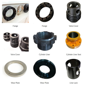
SGPE supports customers looking for a frac pump fluid end supplier, Quintuplex Frac Pump spare parts supplier, frac pump replacement parts or Model 1000 maintenance components.
| Component | Pump Area | Maintenance Focus |
|---|---|---|
| Plunger | Fluid End | Surface Wear |
| Packing | Fluid End | Sealing and Leakage |
| Valve | Fluid End | Erosion and Sealing |
| Valve Seat | Fluid End | Wear and Seat Condition |
| Seals | Fluid End | Leakage |
| Fluid-End Components | Fluid End | Pressure and Wear Areas |
| Crosshead-Related Parts | Power End | Mechanical Condition |
| Bearings | Power End | Temperature and Lubrication |
| Lubrication Components | Power End | Clean Oil Supply |
| Selected Power-End Parts | Power End | Condition-Based Replacement |
For replacement components, provide the pump model, available part number, drawing, dimensions or clear photographs.
Routine maintenance should also monitor packing leakage, valve and seat condition, plunger wear, lubrication, bearing temperature, crosshead condition, vibration and unusual noise.
Maintenance intervals depend on actual field conditions. Higher pressure, abrasive fluids, greater proppant concentration, higher pump speed and longer pumping periods can increase wear.
Quintuplex Frac Pump Price and Quote
Buyers searching for Quintuplex Frac Pump price, 1000 HP frac pump price, hydraulic fracturing pump cost or Quintuplex Frac Pump for sale should compare more than the pump model alone.
The final quotation depends on the technical configuration and complete purchase scope.
| Price Factor | Why It Affects the Quotation |
|---|---|
| Complete Pump or Component | Defines Supply Scope |
| Fluid-End Configuration | Changes Technical Configuration |
| Treatment Fluid | Affects Material and Wear-Part Selection |
| Pressure / Flow Duty | Defines Pump Configuration |
| Installation Type | Trailer, Skid or OEM Interfaces Differ |
| Spare Parts | Changes Total Order Scope |
| Quantity | Influences Production Planning |
| Documentation | Adds Project-Specific Requirements |
| Inspection / TPI | Adds Inspection Scope |
| Replacement Engineering | May Require Dimensional Review |
| Packing | Depends on Shipment Requirements |
| Destination | Influences Logistics Quotation |
A complete Quintuplex Frac Pump RFQ normally produces a more useful quotation than a request for a generic price because the pump, fluid end, installation interfaces and spare-parts scope can be defined correctly from the beginning.
Delivery time also depends on pump quantity, fluid-end configuration, custom interfaces, spare-parts requirements, inspection scope, documentation and packing. SGPE confirms the applicable schedule with the formal quotation.
EPC, Tender and Multiple-Pump Procurement
EPC contractors and tender buyers often need more than a commercial price.
A project RFQ may include the technical specification, equipment datasheet, GA drawing, inspection requirements, documentation list, spare-parts requirement, delivery schedule, packing requirement and project destination.
Providing the complete specification at the beginning helps reduce clarification rounds and allows the proposal to follow the end user’s requirements more closely.
Frac fleet projects may also require several pumps. For a bulk Quintuplex Frac Pump order or multiple-pump package, buyers should define quantity, pump configuration, fluid-end requirements, spare-parts scope, delivery schedule, inspection requirements, documentation and destination.
SGPE can review both the technical and commercial scope before preparing the formal proposal.
Manufacturing, Inspection and Project Documentation
SGPE focuses on oil and gas equipment manufacturing and international project supply.
High-pressure fracturing equipment requires controlled machining, dimensional inspection and reliable component fit. Depending on the agreed purchase scope, technical data, drawings, inspection records and project documentation can be coordinated with the pump supply.
| Document / Record | Supply Basis |
|---|---|
| Technical Data Sheet | Approved Project Configuration |
| GA Drawing | Approved Configuration |
| Dimensional Information | Available |
| Material Documentation | According to Agreed Scope |
| Inspection Records | According to Agreed Scope |
| Test Documentation | According to Agreed Test Plan |
| Certificate of Conformity | When Required and Agreed |
| Operation Information | According to Supply Scope |
| Maintenance Information | According to Supply Scope |
| Spare Parts List | Available |
| Packing Documents | Available |
| Shipping Documents | Available |
| Third-Party Inspection | Can Be Coordinated When Specified |
Inspection, witness and documentation requirements should be identified during the RFQ stage so they can be incorporated into the project plan before production.
Why Choose SGPE for the Model 1000?
SGPE focuses on oil and gas equipment rather than general-purpose industrial pumping. For a Model 1000 project, technical review can cover not only the pump but also the drive arrangement, suction system, high-pressure discharge interfaces and final installation package.
The Model 1000 has clearly defined core data, including 1,000 bhp maximum input power, 100,000 lbf maximum connecting rod load, a 6 in. stroke, a 4.61:1 speed ratio and 3 in. / 3.5 in. fluid-end options.
Customers can source the complete pump together with fluid ends, selected power-end components, wear parts and project spare-parts packages.
For OEM projects, SGPE can review GA drawings, prime-mover information and installation data before production. For replacement projects, existing nameplates, drawings, mounting dimensions and field photographs provide the basis for compatibility review.
SGPE can also coordinate technical submissions, inspection requirements, documentation and commercial quotations for hydraulic fracturing contractors, pressure-pumping companies, equipment manufacturers, EPC firms and international procurement teams.
How to Select and Buy a Quintuplex Frac Pump
For buyers ready to purchase a Quintuplex Frac Pump, selection should begin with actual operating conditions rather than only a model number or target horsepower.
Essential RFQ Data
| RFQ Parameter | Typical Unit / Information |
|---|---|
| Required Treating Pressure | psi / MPa |
| Maximum Design Pressure | psi / MPa |
| Required Pumping Rate | GPM / L/min / m³/h |
| Fracturing / Stimulation Fluid | Slickwater / Gel / Acid / Other |
| Proppant Type | Sand / Ceramic / Other |
| Maximum Proppant Concentration | Project Data |
| Available Horsepower | bhp / kW |
| Prime Mover | Project-Specific |
| Installation Type | Trailer / Skid / OEM |
| Required Quantity | Number of Pumps |
For detailed engineering, also provide fluid temperature, expected pumping hours, duty cycle, transmission information, pump input requirements, mounting footprint, suction and discharge connections, ambient conditions, inspection requirements and technical-documentation requirements.
For a replacement project, include the existing pump model, nameplate, GA drawing, mounting dimensions, shaft position, rotation direction and clear field photographs.
Frequently Asked Questions About Quintuplex Frac Pumps
1. What is a Quintuplex Frac Pump and what is it used for?
A Quintuplex Frac Pump is a positive-displacement reciprocating plunger pump with five pumping cylinders. Oilfield pressure-pumping and well-stimulation companies use this type of equipment to deliver treatment fluid into a well at the pressure and pumping rate required by the treatment program.
Typical applications include hydraulic fracturing, shale oil and shale gas stimulation, horizontal well completions, multi-stage fracturing, plug-and-perf operations and refracturing. Depending on the selected configuration and fluid compatibility, the pump can also support acidizing, selected cementing, workover pumping and other high-pressure well-service operations.
The same equipment may also be described as a five-cylinder frac pump, hydraulic fracturing pump, Quintuplex Plunger Pump, oilfield frac pump, high-pressure plunger pump or well stimulation pump.
2. What are the main specifications of the SGPE Model 1000 Quintuplex Frac Pump?
The SGPE Model 1000 is a horizontal five-cylinder plunger pump designed for demanding oilfield pressure-pumping service. It provides up to 1,000 bhp (746 kW) of input power, a maximum connecting rod load of 100,000 lbf (445 kN) and a 6 in. (152.4 mm) stroke. The speed ratio is 4.61:1.
Overall dimensions are approximately 74.6 × 50.8 × 31.11 in. (1,895 × 1,292 × 792 mm), and the approximate pump weight is 7,231 lb (3,280 kg). SGPE offers 3 in. and 3.5 in. fluid-end configurations for different pressure-flow requirements.
The compact design supports integration into frac trailers, skid-mounted stimulation systems and OEM pressure-pumping packages.
3. What is the maximum working pressure of the Model 1000?
There is no single universal maximum working pressure that applies to every Model 1000 configuration. The final allowable operating pressure depends on the selected fluid end, plunger configuration, pump speed, available horsepower, connection arrangement, treatment fluid and pressure limits of the complete pumping system.
For example, a high-pressure shale fracturing program may require a different pressure-flow operating point from an acidizing, workover or lower-rate well-stimulation job. Selecting a pump only from a headline pressure rating can therefore lead to an incorrect configuration.
Customers should provide both the required treating pressure and pumping rate so SGPE can review the hydraulic duty and determine a suitable Model 1000 configuration.
4. What pumping rate can a 1000 HP Quintuplex Frac Pump deliver?
The pumping rate of a 1000 HP Quintuplex Frac Pump depends on several connected variables, including fluid-end configuration, plunger selection, pump speed, available horsepower and discharge pressure. For this reason, one fixed GPM value cannot accurately represent every Model 1000 installation.
A shale gas fracturing stage that requires high surface flow may use a different operating point from a higher-pressure, moderate-rate treatment. Slickwater, gel viscosity, suction conditions and the overall stimulation package can also influence practical pump performance.
When requesting a quotation, provide the required pumping rate in GPM, L/min or m³/h together with treating pressure, treatment fluid and available horsepower. SGPE will use these conditions to review the applicable pressure-flow duty.
5. What is the difference between a Quintuplex Frac Pump and a Triplex Frac Pump?
The main structural difference is the number of pumping plungers. A triplex frac pump uses three plungers, while a Quintuplex Frac Pump uses five. The five-cylinder arrangement creates more discharge events during each operating cycle.
Under comparable conditions, a quintuplex design can provide smoother fluid delivery, lower pulsation and less pronounced pressure fluctuation. These characteristics can be useful in hydraulic fracturing spreads, multi-stage well stimulation and other demanding pressure-pumping applications.
However, a five-cylinder pump is not automatically the best choice for every project. Buyers should also compare treating pressure, pumping rate, hydraulic horsepower, installation footprint, maintenance requirements, spare-parts availability, package design and lifecycle cost before choosing between triplex and quintuplex equipment.
6. What fluid-end configurations are available for the SGPE Model 1000?
SGPE offers 3 in. and 3.5 in. fluid-end configurations for the Model 1000. The correct option depends on the required pressure-flow operating point rather than nominal fluid-end size alone.
During selection, engineers should consider treating pressure, pumping rate, available horsepower, pump speed, fluid density, viscosity, proppant conditions, temperature, expected pumping hours and duty cycle. A frac pump handling slickwater at high rates may have different requirements from one pumping viscous gel or abrasive proppant slurry.
Customers should therefore provide the actual treatment program and operating conditions. SGPE can then review the fluid-end configuration together with the complete hydraulic and mechanical requirements instead of selecting only by nominal size.
7. Can the Model 1000 handle proppant-laden fracturing fluid?
The Model 1000 can support proppant-laden fracturing service when the fluid end and wear components are selected for the actual operating conditions. Sand and ceramic proppant are commonly used in hydraulic fracturing to help keep created fractures open, but these particles also increase abrasive wear inside the fluid end.
Wear can affect valves, valve seats, plungers, packing, seals and internal flow passages. Proppant concentration, particle size, treatment pressure, pumping rate and total pumping hours all influence maintenance demand.
For a proppant slurry frac pump application, provide the proppant type, particle size, maximum concentration, fluid rheology and expected operating duty. This information helps SGPE review the fluid-end requirements and recommend a more practical spare-parts package for field operation.
8. Can the Quintuplex Frac Pump handle slickwater, linear gel and crosslinked gel?
Yes, different fracturing-fluid systems can be considered subject to technical selection. A frac pump for slickwater fracturing may operate at relatively high surface pumping rates, which makes stable suction flow and correct inlet-system design especially important.
Linear gel and crosslinked gel can have higher viscosity than slickwater. Greater viscosity may affect fluid-end filling, suction pressure loss, valve response and mechanical loading. Proppant added to these fluids introduces an additional abrasive-wear consideration.
For shale oil, shale gas, horizontal well and multi-stage fracturing projects, customers should provide the treatment-fluid type, viscosity or rheology information, additives, proppant conditions, treating pressure and required pumping rate. SGPE can then review whether the selected Model 1000 configuration matches the intended service.
9. Can the Model 1000 be used for acidizing, cementing and workover pumping?
Hydraulic fracturing and well stimulation are the primary applications, but suitable Model 1000 configurations can also support selected acidizing, cementing, remedial pumping and workover operations when the required hydraulic duty falls within the approved operating range.
For acidizing service, fluid chemistry is important because acid type, concentration, additives and temperature can influence fluid-end materials, valves, seats, plungers, packing and seals. Cement slurry introduces different density and rheology considerations, while workover fluids may require another pressure-flow operating point.
Customers should provide the actual fluid properties, treatment pressure, pumping rate, temperature and expected service duration so SGPE can review fluid compatibility and pump configuration before quotation.
10. Can SGPE support trailer-mounted, skid-mounted, OEM and replacement frac pump projects?
Yes. The compact Model 1000 can support trailer-mounted frac pump, skid-mounted frac pump and OEM pressure-pumping equipment projects. Equipment manufacturers can integrate the bare pump into frac trailers, frac pump units, custom stimulation packages and other oilfield pressure-pumping systems.
For OEM projects, SGPE reviews information such as the equipment GA, mounting footprint, prime mover, transmission, input shaft position, rotation direction, suction orientation and high-pressure discharge arrangement.
SGPE also supports replacement Quintuplex Frac Pump projects. For replacement work, customers should provide the existing pump model, nameplate, GA drawing, mounting dimensions, shaft position, drive information and field photographs so dimensional and interface compatibility can be checked before production.
11. Does SGPE supply Quintuplex Frac Pump fluid ends and spare parts?
Yes. In addition to complete pumps, SGPE can support customers requiring Quintuplex Frac Pump fluid ends, replacement parts and maintenance components for Model 1000 equipment.
Typical service requirements may include plungers, packing, valves, valve seats, seals, fluid-end components and selected power-end parts. The actual replacement frequency depends on pressure, pump speed, fluid abrasiveness, proppant concentration, operating hours and maintenance practices.
For accurate part identification, provide the pump model, available part number, drawing, dimensions or clear photographs of the existing component. This is especially important for replacement and fleet-maintenance projects where interface compatibility must be confirmed before supply.
12. How can I get a Quintuplex Frac Pump price or quotation from SGPE?
The Quintuplex Frac Pump price depends on the technical configuration and complete purchase scope rather than the model name alone. Fluid-end configuration, required pressure and flow, treatment fluid, installation type, spare-parts scope, quantity, inspection requirements, project documentation, packing and destination can all affect the final quotation.
For a new Model 1000 requirement, provide the treating pressure, pumping rate, treatment fluid, proppant conditions, available horsepower, installation type, suction and discharge interfaces and required quantity.
For a replacement pump or fluid end, also provide the existing pump model, nameplate, GA drawing, mounting dimensions, drive information and field photographs. Based on these operating conditions and interface requirements, SGPE will review the technical scope and provide a suitable Quintuplex Frac Pump configuration together with the corresponding quotation.
Request a Quintuplex Frac Pump Quote from SGPE
SGPE supplies Quintuplex Frac Pump equipment for hydraulic fracturing, well stimulation, OEM integration and replacement projects. The Model 1000 can be configured for shale oil and gas fracturing, horizontal and multi-stage wells, plug-and-perf operations, refracturing, slickwater and gel treatments, acidizing and other high-pressure oilfield pumping applications.
For a new pump requirement, please provide the required treating pressure, pumping rate, treatment fluid, proppant conditions, available horsepower, installation type, suction and discharge interfaces, and quantity.
For a replacement pump or fluid end, please also send the existing pump model, nameplate, GA drawing, mounting dimensions, drive information and field photographs.
Email: info@sgpe.com
Tel / WhatsApp: +86 186-1599-5239