
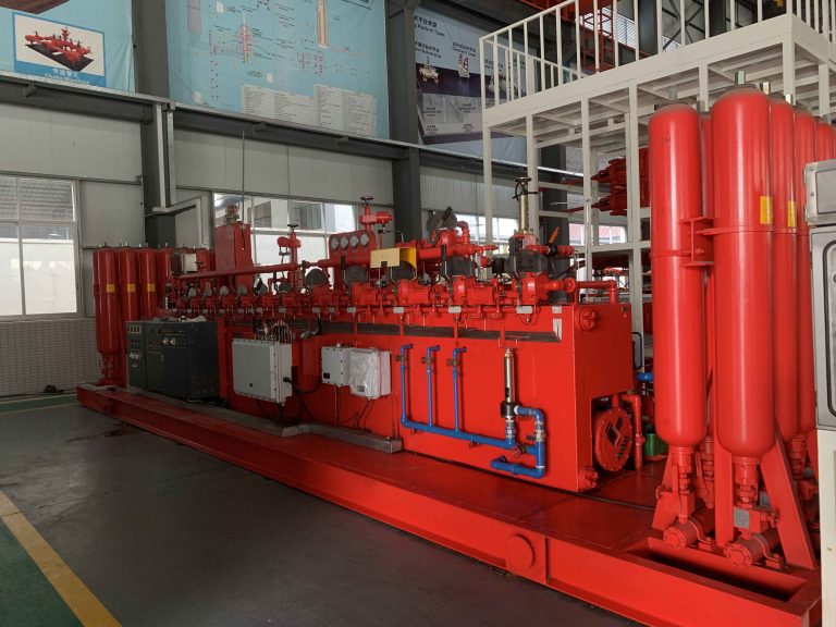
API 16D BOP Control System: Sizing, Selection, Testing and Buying Guide
An API 16D BOP Control System stores, regulates and delivers the hydraulic energy required to operate blowout preventers during drilling and emergency well control operations.
The BOP stack contains wellbore pressure. However, it cannot close a ram preventer, regulate an annular BOP or operate hydraulic choke and kill line valves without a dependable control system.
For this reason, drilling contractors, rig manufacturers, oilfield service companies and well control equipment buyers should evaluate the control package as carefully as the BOP stack itself.
A correctly selected system must provide enough usable hydraulic fluid for the required operating sequence. It must also maintain stable pressure, recharge the accumulator bank within the specified time and allow the crew to operate critical functions from safe locations.
The oilfield industry uses several names for this equipment. Buyers may see it described as a BOP control unit, BOP accumulator unit, BOP closing unit, hydraulic BOP control system, blowout preventer control system, Koomey unit, land closing unit or BOP hydraulic power unit.
Although these terms often refer to similar equipment, the actual scope of supply can vary considerably.
A land drilling rig may need an open-skid accumulator unit with electric and air-driven pumps. By contrast, an offshore surface BOP stack may require a containerized package with marine corrosion protection, hazardous-area electrical equipment and several remote control stations.
The operating environment also affects the design. Desert drilling may require enhanced filtration, sun protection and high-temperature seals. Cold-region projects may need reservoir heaters, insulation and low-temperature hydraulic components.
SGPE supplies project-specific BOP control equipment for new drilling packages, surface BOP stacks, drilling rig upgrades and replacement projects. Before confirming a configuration, the technical review considers operator volumes, the required operating sequence, control distance, available utilities and environmental conditions.
This guide explains how an API 16D BOP Control System works, how engineers size the accumulator bank, which specifications buyers should compare and what information a manufacturer needs before preparing a reliable technical quotation.
Quick Answer: What Does an API 16D BOP Control System Do?
An API 16D BOP Control System uses nitrogen-precharged accumulators, charging pumps, pressure regulators and directional control valves to operate annular and ram blowout preventers.
Engineers size the system from the actual opening and closing volumes of the connected BOPs. They also review the operating sequence, pressure settings, hydraulic line volume, ambient conditions and pump recovery time.
Bottle count, BOP bore size or nominal gallon capacity alone cannot confirm whether a control unit can operate the complete BOP stack.
API 16D BOP Control System at a Glance
| Item | Typical Project Requirement |
|---|---|
| Main function | Store, regulate and deliver hydraulic energy for BOP operation |
| Controlled equipment | Annular BOPs, ram BOPs, hydraulic locks and selected valves |
| Common names | BOP control unit, accumulator unit, closing unit and Koomey unit |
| Energy storage | Nitrogen-precharged hydraulic accumulator bottles |
| Charging sources | Electric, air-driven, diesel or combined pump systems |
| Control methods | Manual hydraulic, pneumatic, electric, PLC or electro-hydraulic |
| Installation | Open skid, weatherproof skid, containerized or split arrangement |
| Remote control | Pneumatic panel, electric panel, PLC panel or touchscreen |
| Main sizing basis | Operator volumes, operating sequence, pressure and line volume |
| Main applications | Land rigs, fixed platforms, jackups and rig modernization |
| Main verification | Capacity calculation, drawdown test, FAT and function testing |
| Main purchasing risk | Selecting only by bottle count or nominal gallon capacity |
This table provides a general overview. The final configuration must follow the actual BOP operator data, approved operating sequence and purchaser specification.
What Is an API 16D BOP Control System?
An API 16D BOP Control System directs pressurized hydraulic fluid to drilling well control equipment.
It allows the crew to operate blowout preventers from a local control manifold, driller’s panel or another approved remote station.
Depending on the BOP stack arrangement, the system may operate annular preventers, single and double ram BOPs, pipe rams, variable bore rams, blind rams, blind shear rams and casing shear rams.
The same package may also control hydraulic ram locks, choke line valves, kill line valves, hydraulic wellhead connectors and selected diverter functions.
The control unit does not contain wellbore pressure directly. Instead, it supplies hydraulic energy to BOP operators and associated valves.
Every BOP model has its own opening volume, closing volume and operating pressure. Consequently, the control package must match the actual equipment installed in the stack.
A generic closing unit may not provide enough usable fluid for a large BOP stack. An unnecessarily oversized package can also create problems because it increases purchase cost, transportation weight, installation footprint and maintenance work without necessarily improving well control performance.
API 16D Scope and Project Requirements
API 16D addresses control systems used with drilling well control equipment and diverter equipment.
Its scope includes hydraulic power supply, accumulator capacity, pressure regulation, operating functions, alarms, testing and system performance.
A complete purchase specification should identify the API 16D edition and addenda required by the contract. It should also define the controlled functions, operating sequences, inspection scope, documentation requirements and applicable local regulations.
Where the equipment will operate in a classified or harsh environment, the specification should state the hazardous-area classification, ambient temperature range, humidity, dust exposure, salt-spray conditions and any special heating or cooling requirements.
A general statement such as “API 16D compliant” rarely provides enough information for detailed system engineering or accurate quotation comparison.
API 16D mainly addresses drilling well control and diverter systems. Coiled tubing, wireline, snubbing, hydraulic workover and other well intervention operations may require separate standards and project-specific control arrangements.
BOP Control System vs. Accumulator Unit vs. Koomey Unit
The terms BOP control system, BOP accumulator unit and Koomey unit often overlap. However, they do not always describe the same supply scope.
BOP accumulator unit
A BOP accumulator unit usually refers to the hydraulic power package.
A typical unit contains accumulator bottles, a hydraulic fluid reservoir, charging pumps, pressure regulators, a main control manifold, gauges, relief valves and isolation valves.
This package stores and supplies hydraulic energy. However, it may not include every remote-control, monitoring or communication component required by the drilling project.
Complete BOP control system
A complete blowout preventer control system normally includes more than the accumulator skid.
Depending on the project, the supply may include local control stations, a driller’s remote panel, a toolpusher’s panel, an emergency control station, hydraulic hoses, electrical cables, pressure transmitters, alarm systems and event-logging functions.
PLC-controlled packages may also require communication interfaces with the drilling rig control system.
Buyers should compare the complete quotation scope rather than assume that every BOP accumulator unit includes the same functions and accessories.
Koomey unit replacement
Oilfield crews often use “Koomey unit” as a general name for a BOP closing unit.
However, different systems may use different pumps, directional valves, regulators, manifolds, hydraulic connections and remote-panel interfaces.
A replacement Koomey unit must match both the hydraulic demand and the existing installation interfaces. The previous model name or accumulator bottle count does not provide enough information on its own.
For a replacement project, the supplier normally needs the existing equipment nameplate, general arrangement drawing, hydraulic schematic, electrical schematic and controlled function list.
The technical review should also cover foundation dimensions, hose connections, remote signals, available utilities and installation photographs.
This interface review reduces field modifications and prevents incorrect assumptions about interchangeability.
Why BOP Control System Reliability Matters
Oil and gas drilling involves changing formation pressures, drilling fluid properties and wellbore conditions.
When formation pressure exceeds the hydrostatic pressure created by the drilling fluid, formation fluids may enter the wellbore. The crew must detect the influx, stop the operation and shut in the well.
At that point, the BOP control system must respond immediately.
Rapid BOP operation
The accumulator bank stores hydraulic energy before the crew needs it. Therefore, the system can operate a BOP function without waiting for the charging pumps to build pressure from zero.
Stored hydraulic energy is important during drilling kicks, gas influxes, tripping operations, electrical power loss and emergency well shut-in.
The same stored energy also supports routine BOP function tests, well control drills and rig commissioning.
Stable hydraulic pressure
Different BOP functions may require different control pressures.
Ram preventers normally operate through a regulated manifold circuit. Meanwhile, the annular BOP usually requires separately adjustable pressure.
The driller must apply enough annular closing pressure to create a dependable seal. However, excessive pressure can increase packing element wear and affect stripping performance.
The annular regulator must therefore maintain stable downstream pressure while hydraulic fluid flows through the manifold, hoses and BOP operator.
Backup charging capability
Many drilling projects require more than one charging source.
A land rig may use an electric motor-driven pump as the primary source and an air-driven hydraulic pump as the backup. If the rig loses electrical power, the pneumatic pump can continue charging the accumulator bank.
Other projects may use dual electric pumps, separate electrical supplies or a diesel-powered emergency pump.
The final pump package must match the available utilities, required recharge time and purchaser’s redundancy philosophy.
Clear emergency controls
Permanent function labels, accurate BOP stack graphics and clearly positioned gauges help the crew identify each control function quickly.
Critical functions may also require protective covers, two-step activation, key-operated controls, warning lights, audible alarms or position feedback.
These safeguards should follow the approved control philosophy and emergency operating procedures.
Continuous readiness
A BOP accumulator unit may remain on standby for long periods. Nevertheless, it must respond immediately when the crew needs it.
The system should maintain pressure, limit hydraulic leakage, monitor pump status and provide clear low-pressure or fault alarms.
Routine function testing and preventive maintenance therefore remain essential.
How Does an API 16D BOP Control System Work?
The operating process begins at the hydraulic fluid reservoir.
First, a charging pump draws control fluid from the reservoir and sends it into the accumulator bottles.
Each accumulator contains a nitrogen precharge. As hydraulic fluid enters the bottle, it compresses the nitrogen and stores hydraulic energy.
The system maintains accumulator pressure between the selected pump start and pump stop settings.
When the driller selects a function, a directional control valve sends pressurized fluid to the corresponding BOP operator chamber.
For example, when the operator selects “close” for a pipe ram BOP, hydraulic fluid enters the closing chamber. At the same time, fluid from the opening chamber returns to the reservoir.
After the operation, the charging pumps restore accumulator pressure.
Main accumulator circuit
The main accumulator circuit stores hydraulic energy at system pressure and supplies fluid to the regulated control circuits.
Ram BOP manifold circuit
The ram manifold circuit supplies regulated pressure to ram preventers, hydraulic ram locks and selected choke or kill line valves.
Annular BOP control circuit
The annular circuit provides separately regulated pressure to the annular preventer.
This arrangement allows the driller to adjust closing pressure for sealing or stripping operations.
Shear ram control circuit
Some BOP stacks require a dedicated high-pressure shear circuit or hydraulic pressure intensifier.
The final design depends on the shear operator volume, required control pressure, drill pipe outside diameter, tubular wall thickness, material grade and required shear-and-seal performance.
The engineering team must review verified BOP operator data and tubular shear information before confirming the circuit.
Pilot control circuit
Pneumatic or hydraulic remote systems may use a separate pilot circuit.
The pilot signal shifts the main hydraulic valve without sending full operating flow through the remote panel.
As a result, the main manifold can remain near the accumulator package while the crew operates the equipment from a safer location.
Typical API 16D BOP Control System Specifications
The following table shows common configuration options for conventional surface BOP control systems.
Final values must follow the confirmed BOP stack, purchaser specification and approved technical datasheet.
| Technical Parameter | Typical Configuration |
| Main hydraulic circuit | Commonly 21 MPa / 3,000 psi |
| Optional shear circuit | Up to 34.5 MPa / 5,000 psi after engineering review |
| Accumulator type | Nitrogen-precharged bladder accumulator |
| Accumulator capacity | Selected from operator volumes and required sequence |
| Charging pumps | Electric, air-driven, dual electric or combined |
| Control architecture | Pneumatic, electro-pneumatic, electric or PLC |
| Annular circuit | Separately adjustable pressure regulator |
| Ram manifold circuit | Regulated hydraulic control circuit |
| Local operation | Manual hydraulic directional valves |
| Remote operation | Pneumatic, hardwired electric, PLC or touchscreen |
| Installation options | Open skid, weatherproof, insulated or containerized |
| Environmental options | Heating, cooling, sunshade, insulation and marine protection |
| Hazardous-area options | Project-specified ATEX, IECEx or NEC components |
| Inspection options | FAT, purchaser witness and third-party inspection |
| Documentation | Drawings, calculations, reports, certificates and O&M manual |
A main circuit of 21 MPa or 3,000 psi is common for conventional surface control units.
When verified BOP operator and tubular data require more pressure, the design may include a separate shear circuit up to 34.5 MPa or 5,000 psi.
These figures serve as engineering references. They do not represent fixed requirements for every API 16D BOP Control System.
Main Components of a BOP Control Unit
Accumulator bottles
Accumulator bottles store hydraulic energy for immediate BOP operation.
Most conventional surface units use nitrogen-precharged bladder accumulators. The bladder separates nitrogen from the hydraulic control fluid.
Buyers should evaluate usable accumulator volume, not only nominal capacity.
The capacity calculation must consider bottle size and quantity, nitrogen precharge, maximum system pressure, pump start and stop pressures and minimum allowable operating pressure.
It must also account for every BOP operator’s opening and closing volume, hydraulic line volume, ambient temperature, expected pressure losses and the required operating sequence.
A unit may have a large nominal capacity but still provide insufficient usable fluid.
Incorrect nitrogen precharge or an unsuitable minimum operating pressure can significantly reduce the hydraulic volume available to operate the stack.
Hydraulic fluid reservoir
The reservoir stores control fluid and receives returning fluid from the BOP circuits.
A practical reservoir should provide adequate working capacity and enough expansion space. It should also include visible level indication, filling and drain connections, cleaning access and suitable filtration.
A protected breather and fluid sampling point help reduce contamination and support routine maintenance.
Environmental conditions influence the final design.
A desert package may require a sunshade, protected breather and high-temperature hydraulic fluid. An offshore unit may need marine-grade coatings and corrosion-resistant fittings.
Meanwhile, a cold-weather package may require reservoir heating, insulation and low-temperature hydraulic fluid.
Hydraulic charging pumps
The charging pumps fill the accumulators and restore pressure after BOP operation.
Common arrangements include electric motor-driven pumps, air-driven hydraulic pumps, dual electric pumps, combined electric and pneumatic pumps or a diesel-powered emergency pump.
Pump selection must consider pressure, flow and recovery time.
A pump may reach the required maximum pressure but still take too long to recharge the accumulator bank.
The engineering review should therefore confirm the initial charging time, recharge time after one BOP operation and recovery time after the required operating sequence.
It should also verify system performance with one charging source unavailable.
For electric pumps, the purchaser should provide the voltage, phase and frequency. For air-driven pumps, the supplier needs the available air pressure, flow and air quality.
Main control manifold
The main control manifold directs hydraulic fluid to each controlled function.
It normally contains directional control valves, pressure regulators, gauges, relief valves, check valves, isolation valves and hydraulic piping.
The panel should display a clear BOP stack diagram. Every control valve should also carry a permanent label that matches the corresponding function.
Typical functions include upper and lower annular BOPs, pipe rams, variable bore rams, blind shear rams, choke line valves, kill line valves and hydraulic ram locks.
The control graphic should follow the physical stack from top to bottom.
Pressure regulators
The annular circuit normally uses a separately adjustable regulator, while the ram BOP circuit uses a regulated manifold supply.
Some projects also require a dedicated shear regulator or pressure intensifier.
The manufacturer should evaluate regulator flow capacity as well as static pressure range.
A regulator may show the correct pressure under no-flow conditions but experience a noticeable pressure drop during rapid operation.
For this reason, the FAT should test regulator performance under representative flow conditions.
Gauges, transmitters and alarms
A BOP closing unit may display accumulator pressure, ram manifold pressure, annular pressure, pump discharge pressure, air supply pressure, pilot pressure and shear circuit pressure.
Mechanical gauges provide direct local indication.
Electronic transmitters may send the same pressure information to a PLC, touchscreen, driller’s panel or rig control system.
Depending on the project, the alarm system may monitor low accumulator pressure, low manifold pressure, low pilot pressure, low reservoir level, pump failure, power loss, high fluid temperature and communication loss.
Remote BOP control panels
A remote BOP control panel allows the crew to operate selected functions away from the main accumulator skid.
Common locations include the driller’s cabin, rig floor, doghouse, toolpusher’s office, offshore control room and emergency control station.
The panel may use pneumatic pilot valves, hardwired electric push buttons, electro-pneumatic controls, a PLC or a touchscreen interface.
Its graphic must match the actual BOP stack. A generic or inaccurate graphic can confuse personnel during an emergency.
Hydraulic hoses and connections
Hydraulic hoses and tubing connect the control manifold to BOP operators and associated valves.
The purchaser should define hose bore, working pressure, length, fire-resistance requirements and external protection.
The RFQ should also state the end connections, connection materials, number of control lines, identification method, temperature rating and offshore corrosion requirements.
Long hoses increase both pressure loss and control-fluid volume.
Consequently, a distant BOP control unit may require larger hoses, higher pump flow or additional accumulator capacity.
Comparison of BOP Control System Types
| System Type | Main Control Method | Main Advantages | Key Design Checks |
| Conventional hydraulic | Manual manifold valves | Simple, direct and easy to inspect | Local access and hose routing |
| Pneumatic remote | Air pilot signals | Common on land rigs and easy to maintain | Air pressure, moisture and pilot distance |
| Electric remote | Push buttons and solenoids | Fast signals and multiple control stations | Area classification and backup control |
| PLC control | PLC, HMI and transmitters | Alarms, data logging and diagnostics | Redundancy, software logic and manual backup |
| Electro-hydraulic | Electrical signals with hydraulic actuation | Flexible remote operation and retrofit potential | Solenoid arrangement and system interfaces |
| Subsea MUX | Electronic commands to subsea pods | Advanced control for floating rigs | Water depth, redundancy and emergency sequences |
The correct control architecture depends on the drilling rig, BOP stack, control distance, available utilities and maintenance capability.
A conventional surface BOP accumulator unit cannot replace a complete subsea MUX control package.
SGPE BOP Control System Options
| Configuration | Control Method | Suitable Application |
| FKQ series | Pneumatic remote control | Conventional land drilling rigs |
| FKDQ series | Electro-pneumatic control | Rig upgrades and multi-panel operation |
| FKD series | Electric or PLC control | Electrically controlled and automated rigs |
| Open-skid package | Local or remote control | Land rigs with easy maintenance access |
| Weatherproof package | Hydraulic, pneumatic or electric | Outdoor drilling environments |
| Insulated package | Pneumatic, electric or PLC | Cold-region oilfields |
| Containerized package | Pneumatic, electric or PLC | Desert, offshore and harsh environments |
| Replacement package | Interface-matched control | Existing Koomey or BOP closing unit replacement |
The exact model, pump arrangement and accumulator capacity must follow the confirmed project requirements.
How to Size a BOP Accumulator Unit
Correct BOP accumulator sizing is one of the most important parts of API 16D control-system design.
BOP bore size and pressure rating alone do not provide enough information.
Two preventers with the same nominal size may have different operator volumes, piston areas and pressure requirements.
Step 1: Identify every controlled function
Prepare a complete control function list.
The list should identify every annular BOP, ram cavity, hydraulic lock, choke line valve, kill line valve, hydraulic connector and diverter function that the system must operate.
Each function must have the correct control valve, pressure circuit and panel label.
Step 2: Confirm BOP operator volumes
Obtain verified opening and closing volumes for every BOP operator.
These figures should come from OEM datasheets, equipment manuals, hydraulic schematics, approved drawings or verified equipment records.
Never estimate operator volume from BOP bore size alone.
Step 3: Define the required operating sequence
The accumulator bank must complete the specified sequence while maintaining enough pressure.
A typical sequence may include closing the largest annular BOP, closing and sealing with a pipe ram, operating hydraulic ram locks and moving hydraulic choke or kill line valves.
When the stack includes a shear ram, the calculation may also need to cover the shear-and-seal function.
The engineering review should confirm the pressure that remains after the complete sequence.
Step 4: Confirm the pressure settings
The sizing calculation should identify the nitrogen precharge, maximum system pressure, pump start and stop pressures and minimum allowable operating pressure.
It should also define the annular pressure, ram manifold pressure, shear pressure and hydraulic lock pressure.
These values determine how much usable hydraulic fluid each accumulator can deliver.
Step 5: Include hydraulic line volume
Long hoses and piping contain a significant amount of control fluid.
The buyer should provide the distance from the control unit to the BOP stack, hose inside diameter, number of control lines, routing arrangement and elevation difference.
Ignoring hydraulic line volume can result in an undersized accumulator bank.
Step 6: Account for the operating environment
Temperature affects nitrogen pressure, hydraulic fluid viscosity, seal behavior and pump performance.
A desert system may need high-temperature seals, sun protection and additional cooling.
By contrast, a cold-region package may require heaters, insulation, low-temperature seals and suitable hydraulic fluid.
The manufacturer should verify system performance at both the minimum and maximum ambient temperatures.
Step 7: Verify pump recovery
Accumulator capacity provides immediate energy, but the charging pumps must restore pressure afterward.
The supplier should calculate or test the initial charging time, recharge after one operation and recovery after the required BOP sequence.
The same review should confirm performance with one pump or charging source unavailable.
A correctly sized accumulator bank with an undersized pump package can still create unacceptable recovery times.
Why Actual BOP Operator Volume Matters
Actual BOP operator volume has a direct effect on accumulator capacity, pump selection and recharge time.
Large-bore annular preventers usually require more control fluid than smaller annular BOPs. However, two models with the same nominal bore and pressure rating can still have different opening and closing volumes.
Ram BOP designs also vary. Pipe rams, variable bore rams, blind rams and shear rams may use different operator areas and control volumes.
For this reason, engineers should not copy operator volumes from another BOP model or estimate them from nominal size.
| Required Operator Data | Why It Matters |
| Fluid volume to close | Determines demand during shut-in operations |
| Fluid volume to open | Supports reopening and complete cycle calculations |
| Recommended control pressure | Defines the regulated circuit setting |
| Maximum allowable control pressure | Prevents operator damage |
| Shear pressure requirement | Determines whether a high-pressure circuit is needed |
| Locking mechanism | Confirms whether a separate lock function is required |
| Operating temperature | Affects seals, fluid viscosity and system performance |
Verified operator data provides a stronger design basis than bottle count, BOP bore size or general industry assumptions.
API 16D Accumulator Drawdown Test
The accumulator drawdown test confirms whether the control system can complete the required operating sequence while maintaining an acceptable final pressure.
The test or calculation should use the confirmed nitrogen precharge, starting pressure, BOP operator volumes, required sequence, minimum allowable pressure, hydraulic line volume and ambient conditions.
The purchaser and manufacturer should agree on the calculation basis and acceptance criteria before FAT.
A clear drawdown review allows buyers to compare usable accumulator capacity instead of relying only on nominal gallons or bottle quantity.
Information Required for an Accumulator Review
| Required Data | Why It Is Needed |
| Complete BOP stack drawing | Confirms the number and position of controlled functions |
| BOP manufacturer and model | Identifies operator and interface requirements |
| Opening and closing volumes | Determines hydraulic demand |
| Annular and ram pressure | Defines regulated circuit requirements |
| Shear data | Determines whether a high-pressure circuit is required |
| Hose length and bore | Adds line volume and pressure-loss information |
| Required operating sequence | Defines usable accumulator capacity |
| Electric power supply | Determines motor and control configuration |
| Compressed-air supply | Determines pneumatic pump and pilot performance |
| Ambient conditions | Defines heating, cooling and material options |
| Remote panel quantity | Defines the control architecture |
| Inspection requirements | Defines FAT and documentation scope |
Providing this information during the RFQ stage allows the manufacturer to prepare a project-specific proposal instead of a generic budget estimate.
API 16D BOP Control System Applications
Land drilling rigs
A typical land rig BOP control system uses an electric motor-driven pump together with an air-driven backup pump.
The package may also include an accumulator bank, hydraulic reservoir, main control manifold, driller’s panel and BOP control hoses.
Open-skid systems provide easy maintenance access. Weatherproof and containerized packages offer greater protection in exposed locations.
Exploration and development drilling
Exploration wells may involve uncertain formation pressures and remote locations. Backup charging, accessible components and a practical spare-parts package therefore become important.
Development drilling often involves repeated rig moves and standardized BOP stacks.
A modular land rig BOP control unit can simplify transportation, installation, hose connection, operator training and maintenance planning across several wells.
High-pressure drilling and shear ram applications
High-pressure wells may require large BOP operators, shear rams and dedicated pressure circuits.
The engineering review should confirm the shear operator volume, required control pressure, tubular shear data, available accumulator capacity, pump recovery time and hose pressure rating.
A separate 5,000 psi shear circuit or hydraulic booster should only be considered after the engineering team reviews verified BOP and tubular data.
Large surface BOP stacks
A 13-5/8-inch 10,000 psi BOP stack may include an annular preventer, single ram BOP, double ram BOP, variable bore rams, blind shear rams and several hydraulic valves.
Meanwhile, a 20-3/4-inch 3,000 psi stack may require substantial hydraulic volume because of its larger annular and ram operators.
For both arrangements, nominal bore size and pressure rating alone cannot determine the required accumulator capacity.
Desert drilling operations
A desert-service BOP control system may require a sunshade, protected reservoir breather, dust-resistant electrical enclosures, enhanced filtration, high-temperature seals and suitable hydraulic fluid.
A containerized package may also require forced ventilation or air conditioning.
The final cooling arrangement depends on the enclosure design, installed heat load and maximum ambient temperature.
Cold-region drilling
A cold-weather BOP accumulator unit may include an insulated control house, reservoir heater, space heaters, heat tracing, low-temperature seals, low-temperature hoses and cold-weather hydraulic fluid.
The supplier should verify pump performance and remote-control response at the minimum design temperature.
Sour-gas locations
The control system normally handles hydraulic fluid rather than wellbore fluid. However, external components may operate in an H2S-containing area.
The purchaser should define the expected exposure, installation area, material requirements, electrical classification, coating system and seal requirements.
Offshore platforms and jackup rigs
An offshore surface BOP control system may require marine-grade coatings, stainless-steel tubing, corrosion-resistant fittings, hazardous-area electrical equipment and several remote control stations.
Limited deck space may require a compact, split, rear-mounted or vertical accumulator arrangement.
For jackup rigs, the technical review should also confirm hose routing, deck loading, lifting arrangements, salt-spray exposure and available utilities.
Rig upgrades and replacement projects
Older BOP closing units may contain obsolete components, leaking manifolds, damaged accumulators or unavailable spare parts.
An upgrade may introduce new charging pumps, increased usable accumulator capacity, PLC monitoring, touchscreen panels, improved alarms, event logging and new hydraulic hoses.
For a replacement project, the new control unit should match the existing foundation, hydraulic connections, remote signals and available rig utilities.
API 16D BOP Control System FAT
A detailed API 16D BOP control system FAT allows the purchaser to verify the equipment before shipment.
| FAT Item | Main Verification |
| Visual inspection | Workmanship, labels, panel layout and equipment arrangement |
| Dimensional inspection | Skid dimensions, lifting points and connection positions |
| Hydraulic leak test | Tubing, hoses, valves, regulators and manifolds |
| Accumulator test | Precharge, pump start, pump stop and pressure stability |
| Pump performance | Charging time, recovery time and independent pump operation |
| Regulator test | Stable annular and ram pressure under flow |
| Functional test | Correct open, neutral and close operation |
| Remote panel test | Commands, indications, alarms and communication |
| Redundancy test | Operation after losing one pump or control path |
| Documentation review | Drawings, calculations, certificates and reports |
Where practical, the manufacturer may connect the control unit to the actual BOP equipment or a suitable simulated hydraulic load.
The FAT may also include purchaser witness points or third-party inspection.
A complete test package can contain the inspection and test plan, FAT procedure, hydraulic pressure test report, pump charging record, accumulator test record, remote panel checklist, alarm test report and final FAT certificate.
Recommended Documentation
The purchaser and manufacturer should agree on the documentation package before production begins.
A typical package includes the general arrangement drawing, hydraulic schematic, electrical schematic, pneumatic schematic, control function list and instrument list.
The final data book may also contain the accumulator sizing calculation, pump charging calculation, remote panel layout and hydraulic hose schedule.
Material certificates, calibration records, pressure test reports, functional test reports and the final FAT report should be included when required by the purchase order.
Depending on the agreed scope, the documentation package may also contain the painting report, operation and maintenance manual, recommended spare-parts list, packing documents and certificate of conformity.
The approved vendor document requirement schedule should define the final deliverables.
BOP Control System Maintenance and Troubleshooting
| Symptom | Possible Causes | Recommended Checks |
| Frequent pump cycling | Leakage, low precharge or incorrect pressure switch | Check hoses, valves, accumulators and pressure settings |
| Slow accumulator charging | Low pump output, dirty filter or restricted suction | Check pump flow, filters and reservoir suction |
| Unstable annular pressure | Worn regulator, contamination or internal leakage | Test the regulator under flow and inspect the fluid |
| Slow remote response | Long pilot line, low air pressure or damaged solenoid | Check air supply, tubing, valves and signals |
| Pressure loss during standby | External or internal leakage | Isolate circuits and locate the leaking component |
| Backup pump fails to start | Utility problem or inadequate maintenance | Test the pump and confirm air or power supply |
Routine maintenance should include accumulator precharge checks, hydraulic fluid inspection, filter replacement, hose inspection and pressure-switch verification.
The maintenance team should also test alarms, remote panel indicators and every charging source.
Use only the specified precharge gas. Never replace nitrogen with oxygen or compressed air.
Complete maintenance records support rig inspections, audits and preventive maintenance planning.
What Affects API 16D BOP Control System Price?
The API 16D BOP Control System price depends on the complete technical and commercial scope.
Accumulator capacity and usable hydraulic volume have a direct effect on system size and cost. Pump quantity, pump type and the number of controlled functions also influence the final quotation.
Control architecture creates another major price difference. A conventional pneumatic control unit has a different cost structure from an electric or PLC-controlled package with pressure transmitters, alarms, event logging and several remote panels.
A dedicated shear circuit, hazardous-area electrical equipment and stainless-steel tubing can further increase the project cost.
Construction requirements also matter. A basic open-skid unit normally costs less than a weatherproof, insulated or air-conditioned containerized package.
Offshore corrosion protection, heating, cooling, hydraulic hose quantity, hose length and the recommended spare-parts package must also be included in the comparison.
Finally, extensive documentation, third-party inspection, purchaser witness testing, special packing and delivery destination can affect the total commercial offer.
Buyers should confirm that every BOP control system supplier has quoted the same scope.
A lower price may exclude remote panels, hydraulic hoses, accumulator calculations, hazardous-area equipment, spare parts, documentation or inspection.
For an accurate quotation, the purchaser should provide complete technical requirements rather than only a nominal gallon capacity.
How to Select an API 16D BOP Control System Manufacturer
A qualified API 16D BOP Control System manufacturer should understand both hydraulic power equipment and BOP operating requirements.
The supplier should be able to prepare accumulator capacity calculations, pump performance calculations and project-specific hydraulic schematics.
It should also be able to develop a clear controlled function list, remote panel layout, FAT procedure and documentation schedule.
Experience with control manifold design, hazardous-area electrical requirements, environmental protection and replacement interfaces is also important.
Before placing an order, buyers should review the accumulator sizing basis, pump recovery calculation, proposed hydraulic schematic and complete controlled function list.
They should also check the remote panel configuration, FAT procedure, documentation scope, spare-parts package and available replacement or retrofit support.
Most importantly, the manufacturer should request the BOP operator volumes, controlled functions, operating sequence and control distance before confirming the system.
A quotation prepared without this information may not reflect the actual drilling project.
SGPE BOP Control System Support
SGPE supplies customized BOP control equipment for new-build, replacement and drilling rig modernization projects.
Available solutions include FKQ pneumatic BOP control units, FKDQ electro-pneumatic control systems and FKD electric or PLC-controlled packages.
The equipment can be supplied as an open-skid accumulator unit, weatherproof package, insulated cold-weather system or containerized BOP control system.
SGPE can also review existing equipment and prepare an interface-matched replacement for selected Koomey-type or conventional BOP closing units.
Depending on the approved configuration, the package may include separate annular and ram circuits, dedicated shear control, remote panels and BOP control hoses.
Project support may also cover accumulator sizing, pump selection, FAT, third-party inspection, documentation and recommended spare parts.
This engineering-based approach helps reduce the risk of insufficient usable volume, slow pump recovery, incorrect control functions, incompatible hose connections and installation conflicts.
Related Well Control Equipment
A complete drilling well control package may also include annular BOPs, ram BOPs, API 16D BOP control hoses, drilling spools, choke and kill manifolds and BOP pressure test units.
The BOP control system opens and closes the preventers and hydraulic valves.
By contrast, a BOP pressure test unit generates the wellbore-side pressure required for an approved pressure test.
These products should work together as part of the well control package, but each item performs a separate technical function.
Information Required for an SGPE Quotation
| RFQ Information | Details to Provide |
| BOP stack | Complete arrangement from top to bottom |
| BOP equipment | Manufacturer, model, size and pressure rating |
| Operator volumes | Opening and closing volume for every function |
| Controlled functions | Annular, rams, locks and hydraulic valves |
| Operating sequence | Required normal and emergency operations |
| Shear requirements | Tubular data and required shear pressure |
| Pressure requirements | Accumulator, annular, ram and shear pressure |
| Remote panels | Quantity, location and preferred control method |
| Electrical supply | Voltage, phase and frequency |
| Pneumatic supply | Pressure, flow and air quality |
| Hydraulic hoses | Length, bore, pressure and end connections |
| Installation | Skid, container, split or retrofit arrangement |
| Environment | Temperature, humidity, dust, salt spray and altitude |
| Area classification | Zone, division, gas group and temperature class |
| Inspection | FAT, third-party inspection and witness points |
| Documents | Drawings, calculations, certificates and manuals |
| Commercial data | Quantity, Incoterm and delivery destination |
Providing complete RFQ information allows SGPE to prepare a project-specific technical proposal instead of a generic budget price.
Frequently Asked Questions About API 16D BOP Control Systems
1. What is an API 16D BOP Control System?
An API 16D BOP Control System stores, regulates and directs hydraulic fluid to drilling well control equipment. It may operate annular BOPs, ram BOPs, hydraulic locks and selected choke or kill line valves.
A complete package can include an accumulator bank, hydraulic reservoir, charging pumps, regulators, control manifold, gauges, alarms and remote panels.
The required configuration depends on the BOP models, operator volumes, operating sequence, control distance and rig utilities. Land rigs, offshore platforms, jackups and rig upgrade projects may therefore require different control arrangements.
2. What is the difference between a BOP control system and a BOP accumulator unit?
A BOP accumulator unit usually refers to the hydraulic power package that stores and supplies pressurized control fluid. It normally includes accumulator bottles, pumps, a reservoir, regulators and a main manifold.
A complete BOP control system may also include driller’s panels, emergency control stations, hydraulic hoses, electrical controls, pressure transmitters, PLC monitoring and alarms.
When comparing quotations, buyers should confirm whether each supplier has included only the accumulator skid or the entire control package.
3. Is a Koomey unit the same as a BOP control unit?
Oilfield crews often use Koomey unit as a general name for a BOP closing unit or accumulator unit.
However, systems may use different pumps, valves, regulators, hydraulic connections and remote-control interfaces.
For a Koomey unit replacement, provide the existing nameplate, drawings, controlled functions, foundation dimensions, hose connections, remote signals and installation photographs. These details help the supplier prepare an interface-matched replacement for a land rig, offshore installation or drilling rig modernization project.
4. How do engineers calculate BOP accumulator capacity?
Engineers calculate BOP accumulator capacity from the hydraulic demand of the connected well control equipment.
The review includes each BOP operator’s opening and closing volume, the required operating sequence, nitrogen precharge, pump settings, minimum allowable pressure and hydraulic line volume.
Temperature, pressure losses and reserve capacity also affect the result.
BOP bore size, pressure rating, bottle count or nominal gallon capacity alone cannot determine the correct system size. Buyers should request a documented BOP accumulator sizing calculation before approving the configuration.
5. What is usable accumulator volume?
Usable accumulator volume is the amount of hydraulic fluid that the accumulator bank can deliver between its starting pressure and the minimum acceptable operating pressure.
This value differs from the total nominal volume shown on the system nameplate.
Incorrect nitrogen precharge, unsuitable pressure settings or long hydraulic hoses can reduce the volume available to operate the stack.
Usable volume becomes particularly important for large-bore annular preventers, multi-cavity ram BOP stacks, long-distance control lines and offshore surface BOP control systems.
6. Can one BOP control unit operate both annular and ram BOPs?
Yes. A correctly configured BOP control unit can operate annular BOPs, pipe rams, variable bore rams, blind shear rams, hydraulic locks and selected hydraulic valves.
The annular preventer normally uses a separately adjustable pressure circuit, while ram preventers operate through a regulated manifold circuit.
A stack with a shear ram may also require a dedicated high-pressure circuit or pressure intensifier. The final design must follow verified operator volumes, control pressures and tubular shear data.
7. Why does a BOP accumulator unit need more than one pump source?
A second charging source improves system availability during a power or equipment failure.
A conventional land rig may use an electric pump as the primary source and an air-driven hydraulic pump as the backup. Other projects may use dual electric pumps or a diesel-powered emergency pump.
The selected arrangement should match the available rig utilities, required recharge time and redundancy philosophy.
Pump capacity also matters. A pump may reach the required pressure but still take too long to restore the accumulator bank after a BOP operation.
8. What is a remote BOP control panel?
A remote BOP control panel allows the crew to operate selected well control functions away from the main accumulator skid.
Common locations include the driller’s cabin, rig floor, doghouse, toolpusher’s office and emergency control station.
The panel may use pneumatic pilot valves, electric push buttons, electro-pneumatic controls or a PLC touchscreen. It may also display accumulator pressure, annular pressure, manifold pressure, pump status and alarms.
The panel graphic should match the physical BOP stack so the crew can identify each function quickly.
9. What is a PLC BOP control system?
A PLC BOP control system uses a programmable logic controller to manage function commands, pressure indications, pump status, alarms and event records.
It can provide clearer diagnostics, faster signal transmission and easier integration with the drilling rig control system.
However, the design should still include suitable redundancy, manual operation and a defined response to power or communication failure.
PLC control is commonly considered for automated drilling rigs, offshore platforms, containerized BOP control packages and modernization projects that require improved monitoring.
10. Can the system use a 3,000 psi main circuit and a 5,000 psi shear circuit?
A 21 MPa or 3,000 psi main hydraulic circuit is common for conventional surface BOP control units.
Some blind shear ram or casing shear ram applications may require a separate circuit up to 34.5 MPa or 5,000 psi.
Before adding a high-pressure shear circuit, the engineering team must review the operator volume, required pressure, pipe dimensions, tubular grade and verified shear data.
The hoses, valves, regulator and control components must also match the approved pressure rating.
11. What should an API 16D BOP control system FAT include?
An API 16D BOP control system FAT normally covers visual and dimensional inspection, hydraulic leak testing, accumulator precharge verification, pump charging performance, pressure regulation and function testing.
The test should also verify remote panel commands, alarms, pressure indications and backup pump operation.
Where practical, the manufacturer may connect the unit to the actual BOP equipment or a representative hydraulic load.
Purchaser witness points, third-party inspection and the required test records should be agreed before production begins.
12. What information should I include in an API 16D BOP Control System RFQ?
A complete API 16D BOP Control System RFQ should include the BOP stack arrangement and the manufacturer, model, size and pressure rating of each preventer.
The inquiry should also provide operator volumes, controlled functions, operating sequence, pressure requirements, shear data, hose lengths and remote panel quantity.
Electrical supply, compressed-air supply, ambient temperature and hazardous-area classification are also required.
Finally, state the FAT scope, documentation requirements, quantity, Incoterm and delivery destination. Complete information allows SGPE to prepare a project-specific quotation instead of a generic accumulator-unit price.
Technical References
The final system design should be based on the API 16D edition and addenda specified in the purchase contract, together with the approved purchaser specification.
Model-specific BOP operator volumes, control pressures and shear requirements should come from the relevant OEM datasheets, equipment manuals, approved drawings or verified equipment records.
Project-specific hydraulic schematics, electrical diagrams, control function lists and inspection requirements should form part of the final technical review.
Request an API 16D BOP Control System Quotation
The correct API 16D BOP Control System must match the actual BOP stack, operating sequence, rig utilities and drilling environment.
A large accumulator bank cannot correct inaccurate operator data, insufficient pump flow or an unsuitable control arrangement.
Before placing an order, verify the accumulator sizing calculation, usable hydraulic volume, pump charging performance, backup charging source and pressure-control arrangement.
The technical review should also confirm the shear ram requirements, remote panel configuration, hydraulic hose specifications, environmental protection, FAT scope, documentation and spare-parts package.
The inquiry should also include the remote panel quantity, electrical and pneumatic supplies, ambient temperature range, hazardous-area classification, hose lengths, connection specifications and applicable standards.
Finally, state the inspection scope, documentation requirements, order quantity, Incoterm and delivery destination.
E-Mail:
info@sgpe.com
